

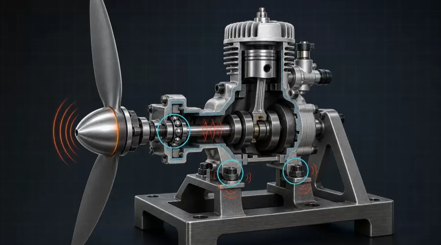
Quick answer: Stop a model engine when vibration is new, increasing, accompanied by a damaged propeller, loose hardware, visible shaft wobble, abnormal heat or mechanical noise. With the engine cool and unable to start, inspect the propeller and spinner first, then the shaft/adapter, engine mount, exhaust and fuel hardware, combustion baseline and bearings. A balanced propeller cannot repair a bent shaft, loose mount, worn bearing or unstable combustion, and a soft mount can move a problem rather than solve it. Use the exact engine, propeller and model manuals for limits and torque values.
Key principle: vibration is evidence, not a part number. Diagnose the source and the path separately: what creates the force, and what lets that force reach the stand, airframe, radio system or driveline?
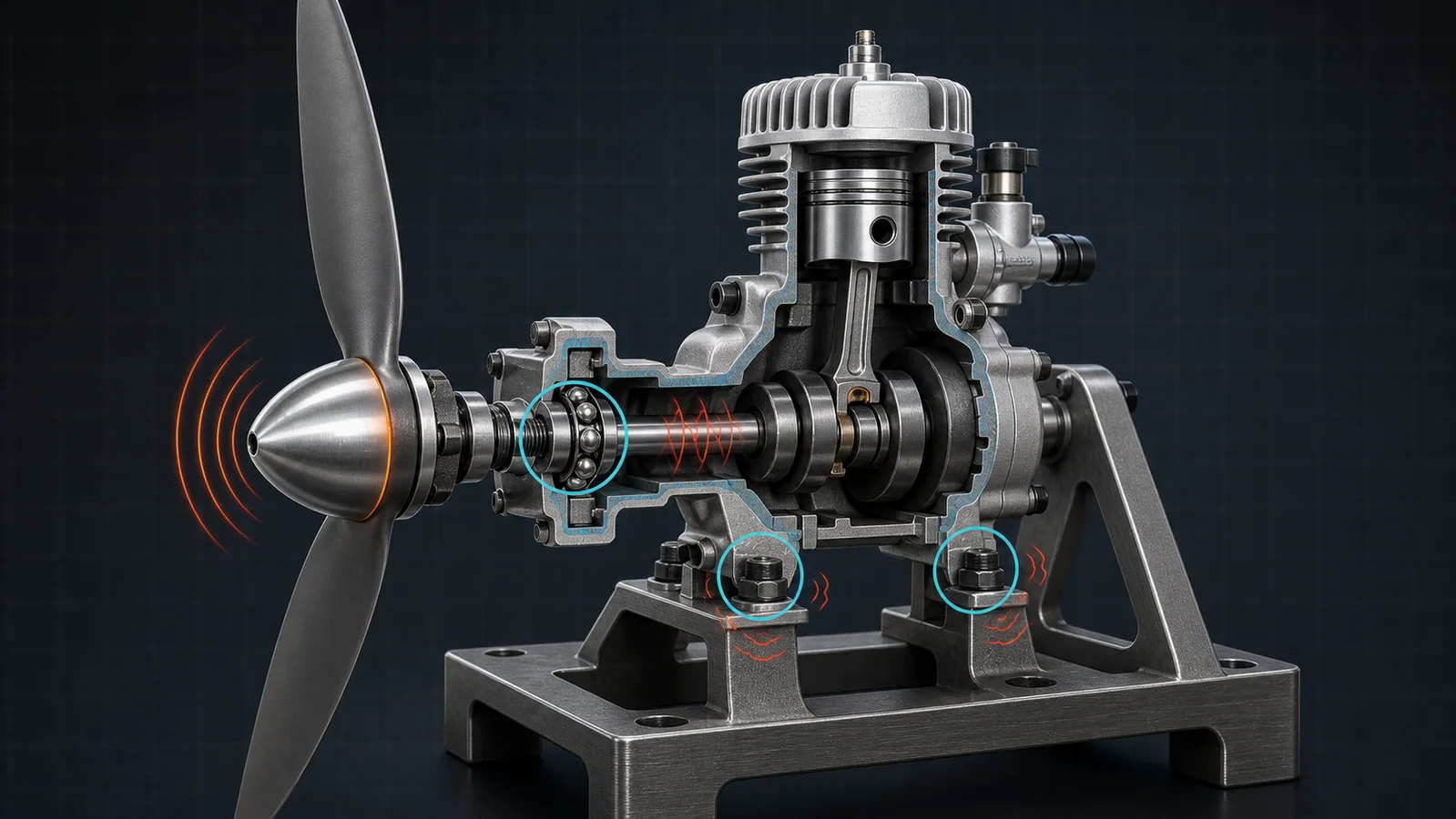
Is some model-engine vibration normal?
Yes. A reciprocating engine does not create perfectly steady torque. Pistons accelerate and reverse direction, connecting rods change angle, combustion pressure rises in pulses, and single- or twin-cylinder layouts cannot cancel every force. A rigidly mounted running engine therefore transmits some vibration even when it is healthy. “It moves” is not, by itself, a diagnosis.
What matters is the baseline. A healthy installation should behave consistently for the same fuel, propeller or flywheel, temperature, mounting and rpm. A new frequency, a sudden increase, a narrow speed band that becomes severe, hardware that repeatedly loosens, a blurred or orbiting spinner, a changed exhaust note, loss of power, metal particles or rising bearing temperature all justify stopping and investigating.
Large model-aircraft engines deserve extra caution. The British Model Flying Association notes that larger engines may produce high-amplitude, low-frequency vibration unlike smaller model engines and advises vibration-proofing, secure ground testing and attention to anything that loosens. This does not mean “run it until it smooths out.” It means the installation must be proven under the exact manufacturer and field procedures before operation.
The same reasoning applies to a display stand. An inline-twin nitro model, a four-cylinder gasoline model and a miniature V8 have different firing patterns and mounts. A visual comparison across architectures is not a pass/fail test.
Five families of model-engine vibration
Use five source families so that one familiar symptom does not dominate the diagnosis.
| Source family | Typical clues | What the clue cannot prove | First safe check |
|---|---|---|---|
| External rotating parts | Vibration rises strongly with rpm; spinner or adapter appears to orbit; prop was changed or damaged | That adding balance weight is approved | Power isolated: inspect prop, hub, spinner, adapter seating and manufacturer-specified static balance |
| Mount and structure | Feet, firewall, stand, exhaust or brackets visibly move; fasteners loosen; one speed band is much worse | That rubber isolation is the cure | Check cracks, flatness, fastener condition, clearances and exact mount instructions |
| Combustion or fuel | Uneven exhaust note, misfire, rpm hunting, temperature or smoke changes with the shake | That the crankshaft is bent | Return ignition, plug, fuel and mixture to the documented baseline |
| Shaft and bearings | Rough hand rotation, radial play, scraping, heat, metal debris or repeatable runout with external parts removed | Which bearing has failed or whether service is authorized | Cool, unpowered inspection and maker-defined play/runout measurement |
| Driven system | Vibration begins after clutch, coupling, gearbox, fan, pulley or flywheel work | That the engine itself is healthy | Inspect alignment, fasteners, keys, set screws and approved component balance |
More than one family can be present. A slightly unbalanced spinner may excite a flexible stand near its natural frequency. A loose mount may then amplify normal firing pulses. A rich misfire may shake the structure enough to reveal a cracked exhaust bracket. Treat each observation as a branch in a fault tree, not a verdict.
When should you stop the engine immediately?
Stop immediately for a cracked, chipped, warped or delaminating propeller; loose propeller nut or spinner; visible shaft or hub orbit; contact between spinner and propeller; loose or cracked engine mount; fuel leak; abnormal metallic knock; smoke from a bearing or electrical starter; sudden power loss; rapid heat increase; or vibration severe enough to move the stand or affect controls.
Do not stand in the propeller plane. BMFA guidance requires a suitable, balanced and undamaged propeller, a restrained model during starting, and no person in line with the rotating propeller. O.S. likewise warns that an unbalanced propeller or spinner can weaken the airframe and affect radio-control safety. A propeller blade failure can create a destructive imbalance; AOPA describes the same mechanism at full scale. The size differs, but the reason to clear the rotating plane does not.
Before inspection:
- Shut down by the manufacturer-approved method.
- Disconnect ignition, glow power, starter battery or electric drive so the engine cannot start.
- Close the fuel supply and clean spills.
- Wait for the engine, exhaust and bearings to cool.
- Remove the propeller only with the correct tools and procedure; mark its original orientation if the manual makes orientation relevant.
- Never turn a suspect system with fingers in a possible propeller or flywheel path.
Propeller, spinner, adapter and runout checks
External rotating parts are checked first because they are accessible and their centrifugal force grows rapidly with speed. SKF's vibration guide explains that pure mass imbalance often appears primarily at once-per-revolution frequency and increases with speed. That is a useful engineering clue, but a phone vibration app or an ear cannot prove pure imbalance: misalignment, looseness and resonance can create similar patterns.
1. Inspect the propeller as a safety component
Use only a propeller type, diameter, pitch, material and rpm rating approved for the exact engine and application. The FAA's amateur-built testing handbook calls for inspection of cracks, nicks, warpage, hub damage and blade tracking; those inspection principles are useful, but its full-scale dimensions and repair permissions are not model specifications. BMFA expressly says damaged model propellers must not be used and all model propellers should be carefully balanced.
Do not repair a structurally suspect propeller because it can be made to balance. Static balance only compares the mass moment of the blades around an axis. It cannot certify laminate integrity, hub fit, blade stiffness, aerodynamic equality or rpm capability.
2. Verify the hub and spinner stack
Remove oil, burrs and trapped debris from seating faces using the maker-approved method. Check that the propeller bore fits the specified shaft or adapter and that washers and locknuts are present in the correct order. O.S. warns that spinner notches must clear the propeller roots and that the spinner itself needs adequate strength and balance. A centered-looking spinner cone can still be distorted by an uneven backplate or incorrectly seated adapter.
3. Separate static balance from dynamic behavior
A manufacturer-approved model propeller balancer can reveal static heavy-side bias. Dynamic imbalance includes the assembled propeller, hub, spinner, adapter and their axial distribution. The FAA powerplant handbook explains that dynamic balancing measures vibration and phase on the assembled propulsion system, while also warning that balancing will not correct defective, worn or loose parts. Do not copy an aviation balance-weight procedure onto a model. Use only the model engine and propeller makers' approved method.
4. Check runout without guessing a universal limit
With external rotating parts removed and ignition disabled, inspect the shaft and adapter for visible damage and smooth rotation. If the manual supplies a dial-indicator location and maximum runout, measure exactly there. A measurement taken on a threaded tip, dirty taper or removable adapter can falsely accuse the crankshaft. No universal model-engine runout limit is safe across the RC engine models category.
A small two-stroke nitro engine with a clutch or flywheel presents a different rotating stack from an aircraft propeller installation. Inspect the driven parts named in that product's manual rather than transferring propeller procedures.
Engine mounts, fasteners and structural resonance
A mount has two jobs: hold alignment under load and manage how force reaches the surrounding structure. Too little stiffness can permit excessive motion; too much local stiffness can concentrate stress. Rubber is not automatically better. An unapproved soft mount may let the carburetor, exhaust, linkage or fuel line move relative to the engine and may create a new resonance.
Inspect the complete load path:
- engine feet or crankcase lugs for cracks, fretting and distorted holes;
- mount rails, stand plates and firewall for cracks, crushed material and lost flatness;
- bolts, washers, locknuts and thread-locking method against the exact manual;
- exhaust supports, starter brackets, generators, pumps and fuel tanks for independent movement;
- radio receivers, batteries, linkages and wiring for chafing or vibration exposure;
- adequate clearance so no spinner, flywheel, coupling or exhaust touches the frame.
Do not tighten by feel until threads yield, and do not add threadlocker where fuel, heat, plastic or service instructions prohibit it. Saito recommends reliable propeller balance and gives a specific anti-loosening instruction for its named engine's mounting screws. That supports the principle of following the maker; it is not permission to apply the same adhesive or torque to every model.
A narrow severe rpm band may be resonance: the forcing frequency approaches a natural frequency of the engine-mount-stand system. SKF describes critical speed as the point where rotational excitation aligns with a shaft/bearing system's natural frequency. A resonance can amplify a modest imbalance, but the safe response is not to race through it repeatedly. Stop, remove looseness and damage, verify the approved installation, then consult the maker if the operating range still intersects a severe response.
How to separate combustion roughness from mechanical vibration
Combustion-related roughness tends to follow misfire, uneven firing or rpm hunting. Listen for changes in exhaust cadence and watch only from a safe position for changes in smoke, temperature and throttle response. If vibration changes sharply when mixture, ignition or fuel delivery becomes unstable, restore the documented baseline before condemning a bearing.
For a glow engine, confirm the correct plug and igniter using the glow-plug guide. For both glow and spark systems, check the tank, clunk, vent and pressure path. A blocked vent, air leak, intermittent ignition or flooded cylinder can create uneven torque that looks mechanical.
Temperature is another discriminator, not a verdict. A lean or poorly cooled engine can lose lubrication margin and change clearances; use the overheating and cooling guide rather than tuning by sound alone. If compression or sealing changed after service, the compression and leak-down guide helps separate leakage evidence from a vibration guess.
A multi-cylinder engine can also shake when one cylinder is weak. Confirm plug, ignition lead, valve action, temperature contribution and fuel distribution using the maker's method. Never pull a high-voltage lead or reach into a running installation to identify a cylinder unless the exact service procedure provides a safe remote test.
What vibration clues point toward a bearing or crankshaft?
Bearing suspicion becomes stronger when several independent clues agree: roughness during slow unpowered rotation, repeatable radial or axial play beyond the maker's limit, heat concentrated at a bearing housing, scraping or rumbling that persists after external rotating parts are removed, contaminated lubricant, metal particles, a damaged seal, or measured shaft runout at the specified surface.
Noise alone is weak evidence. Gear mesh, piston slap, valve gear, clutch shoes, fan blades, exhaust brackets and starter mechanisms can imitate bearing noise. Similarly, a balanced propeller can reduce force enough to mask a marginal bearing without making it serviceable.
SKF notes that imbalance increases dynamic bearing load and can contribute to fatigue. That describes a mechanism: continued imbalance can damage bearings. It does not prove that every vibrating engine already has a failed bearing. The diagnostic sequence is therefore:
- remove external damage, looseness and incorrect assembly;
- verify fuel, ignition and combustion baseline;
- measure play/runout only where the exact manual specifies;
- inspect lubricant and internal parts only if the maker permits disassembly;
- replace bearings, shaft or crankcase as a matched service decision—not as a sound-based guess.
Do not hammer a bearing out, heat a crankcase or press on a rolling element without the service procedure. Small model parts are easy to distort, and a replacement bearing with the same outside dimensions may differ in clearance, cage, seal, speed or fit.
A controlled model-engine vibration diagnosis
- Freeze the evidence. Record engine model, propeller/flywheel, fuel, ignition, mount, recent work, temperature and the rpm region where the symptom occurs.
- Apply the stop rule. Any damaged propeller, loose mount, leak, metal noise, severe runout or rapid heat rise ends the run.
- Make the engine unable to start. Isolate fuel and all starting/ignition energy, then let it cool.
- Inspect external rotating parts. Check propeller, spinner, hub, adapter, flywheel, clutch and coupling according to their manuals.
- Inspect the load path. Check engine feet, stand/firewall, fasteners, exhaust, tank, linkages, wiring and clearances.
- Rotate by hand safely. Feel for repeatable roughness and listen for contact; never use the propeller as a lever on a suspect or energized engine.
- Measure only defined quantities. Use the maker's runout, play, torque and balance locations. If no limit exists, record `UNKNOWN` and ask the maker.
- Restore the operating baseline. Correct plug/ignition, fuel, cooling and mixture; change one approved variable at a time.
- Perform a restrained confirmation only if permitted. Clear the rotating plane, use the field/manufacturer restraint and observe remotely where possible.
- Stop on recurrence. Do not keep running to collect more dramatic evidence. Escalate to service when the source remains unknown.
| Observation | Supports | Does not prove | Decision |
|---|---|---|---|
| Vibration began immediately after prop/spinner change | Assembly, fit, tracking or balance deserves first inspection | The crankshaft is healthy | Stop; inspect and restore the approved rotating stack |
| Severe only in one narrow rpm band | Possible structural or shaft-system resonance | That the engine is safe above the band | Stop repeated sweeps; verify mount and consult maker |
| Shake follows misfire and rpm hunting | Combustion/fuel/ignition branch | That all mechanical parts are good | Restore baseline, then recheck mechanically |
| Rough hand rotation with prop removed | Internal contact, bearing, gear or shaft branch | Which component failed | Do not run; follow service inspection |
| Mount bolt repeatedly loosens | Incorrect torque/locking, damaged thread, excessive force or flexible joint | That stronger adhesive is safe | Inspect thread and load path; use exact fastener method |
Facts, inferences, supplier claims and unknowns
- Fact: a reciprocating model engine produces periodic forces; some vibration is inherent.
- Fact: propeller damage, imbalance, poor tracking, loose parts and shaft-system faults can increase transmitted vibration.
- Reasonable inference: a symptom appearing directly after one assembly change makes that change the first inspection branch, not automatic proof of cause.
- Supplier instruction: propeller size/rating, torque, thread locking, shaft play, runout, bearing fit and acceptable test procedure are model-specific.
- Unknown without instruments and limits: whether a visible shake exceeds an allowable level or whether 1× vibration is pure imbalance.
- Unknown without controlled isolation: whether a sound comes from a bearing, gear, clutch, exhaust, valve train or structure.
This guide does not authorize flight, high-rpm testing, field balancing, propeller repair, internal engine disassembly or modification. It supplies a decision framework. Where the exact manual is missing, the correct numerical answer is unknown—not a value borrowed from another engine.
Frequently asked questions
Can an unbalanced propeller damage a model engine?
Yes. Imbalance increases cyclic force on the shaft, bearings, mount and structure. Replace a damaged propeller and use only the maker-approved balance and installation method; balance cannot certify a cracked or unsuitable propeller.
Does vibration at one rpm mean resonance?
It can support a resonance hypothesis, especially when the response is narrow-band, but it does not prove the source. Looseness, combustion instability and rotating-part faults must be checked first.
Should I use rubber mounts to reduce vibration?
Only if the exact engine and installation maker approves them. Added compliance can change alignment, fuel or linkage movement and natural frequency, so an unapproved soft mount may amplify a problem.
How can I tell if a model-engine bearing is bad?
Look for multiple clues: rough unpowered rotation, maker-defined excess play, localized heat, persistent rumble, contaminated lubricant, particles or measured runout. Sound alone is not enough.
Can I measure model-engine vibration with a phone?
A phone can record a repeatable trend on the same mount, but its sensor, placement and sampling are not a certified limit. Do not use an app to declare a damaged propeller or engine safe.
Why do mounting bolts keep coming loose?
Possible causes include incorrect torque or locking method, damaged threads, loss of clamp load, flexible mounting surfaces or excessive vibration. Inspect the joint and follow the exact fastener specification instead of simply adding stronger adhesive.
Conclusion
Good vibration diagnosis is an isolation process. Begin with safety and the external rotating stack, then follow the force through the mount and structure, restore combustion to its documented baseline, and investigate bearings or shaft damage only when independent evidence points there. Record one change at a time and stop when the source is unknown. That method protects both the model and the operator while producing a diagnosis that another builder can verify.
References
- FAA Aviation Maintenance Technician Handbook—Powerplant, Volume 2
- FAA AC 90-89B: Amateur-Built Aircraft and Ultralight Flight Testing Handbook
- BMFA Handbook: General Model Safety
- BMFA Handbook: Safety Advice for Specific Model Types
- O.S. Engines FR5-300 Instruction Manual
- Saito FA-30SH Instruction Manual
- SKF Vibration Diagnostic Guide
- Academy of Model Aeronautics Safety Handbook
- AOPA Propeller Safety Spotlight
For a symptom-first starting sequence, use the model engine won't-start troubleshooting guide before changing multiple settings. To compare operating methods and assembly levels after diagnosis, browse model engine kits.
Leave a comment