

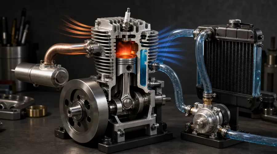
Quick answer: A hot miniature engine is not automatically an overheating engine. Diagnose the complete heat path before changing parts: confirm the measurement, compare it with the exact maker's limit and sensor location, then check mixture and load, oil and friction, heat transfer into the cylinder or water jacket, airflow across fins or radiator, and coolant circulation. There is no single safe temperature for every glow, gasoline, diesel, hit-and-miss, air-cooled, or water-cooled model engine.
Key principle: Heat follows the whole path, not the loudest symptom. A larger radiator cannot repair a lean mixture, a faster fan cannot overcome blocked fins, and a low infrared reading on a shiny head does not prove the metal is cool.
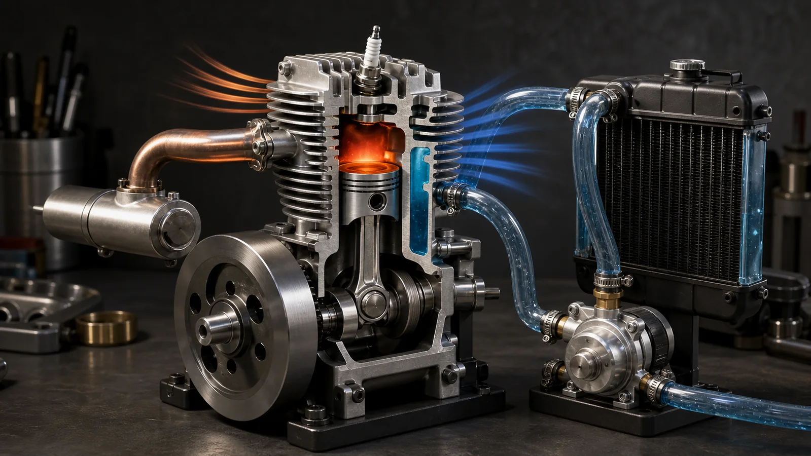
Is the model engine normally hot, or actually overheating?
Combustion makes intense heat. Some leaves through the exhaust; some travels through the piston, cylinder, head, bearings, oil, and cooling system before reaching the surrounding air. The U.S. Federal Aviation Administration explains the same basic energy problem for larger piston engines: excessive temperature can cause power loss, oil consumption, detonation, and permanent damage. The scale is different, but the heat-transfer logic remains useful for a working miniature internal-combustion engine.
Start with evidence, not touch. A cylinder head that is uncomfortable to touch may still be operating as designed, while a local hot spot can exist even when a nearby surface looks acceptable. Stop the run immediately if you see a maker-defined temperature warning, loss of lubrication, cooling-flow loss, boiling or sudden coolant discharge, tightening or seizure, detonation-like sound, uncontrolled speed, smoke from non-exhaust components, or a rapid loss of power. Let the engine cool naturally and investigate before restarting.
Do not import a temperature number from a different engine. A ringed gasoline four-stroke, an ABC glow engine, a diesel model engine, and a low-speed hit-and-miss engine can have different materials, clearances, fuels, measurement points, and limits. Treat the manufacturer manual for the exact engine as the governing source. If no credible limit is published, record a conservative baseline during known-correct operation and use trend changes as a diagnostic signal rather than inventing a universal red line.
The five-part heat path
NASA describes three fundamental heat-transfer modes: conduction through material, convection between a surface and a moving fluid, and radiation from a hot surface. An operating model engine adds heat generation and measurement to that chain. For troubleshooting, divide the system into five parts.
1. Measurement
First ask whether the reading is comparable. A thermocouple under a plug, a contact probe on the head, an infrared thermometer aimed at black paint, and the same infrared thermometer aimed at polished aluminum can disagree. The FAA's maintenance handbook notes that cylinder-head probes are installed at a defined location, often the hottest cylinder determined during testing, and gives an ambient-temperature sanity check before operation. The lesson is simple: location and instrument method are part of the specification.
2. Heat generation
Combustion setting and mechanical load determine how fast heat enters the system. The O.S. Engines technical FAQ warns that closing a glow-engine needle too far creates a lean mixture, reduces the fuel's cooling effect, and can overheat the engine. Ignition timing, unsuitable fuel, excess propeller or drivetrain load, restricted exhaust, and sustained high speed can also raise heat generation. These causes must be checked before assuming that the radiator or fins are too small.
3. Conduction and internal cooling
Heat must conduct from the chamber and moving parts into the head, cylinder, oil, or water jacket. Poor contact, scale inside a jacket, an incorrect gasket, damaged surfaces, or insufficient oil can interrupt that path. The FAA notes that oil contributes to internal engine cooling as well as lubrication. That does not make aircraft oil instructions a model-engine fuel recipe; it means lubrication condition belongs in a thermal diagnosis. Use only the fuel and oil type specified by the engine maker.
4. External airflow
Air-cooled fins work only when air reaches them and the warmed air can leave. The FAA handbook explains that baffles route air across cylinder fins, while the maintenance handbook shows that properly placed baffles and deflectors can reduce the cooling-air volume required by preventing air from bypassing the hot surfaces. A fan pointed vaguely at the engine may move plenty of air around the bench but little through the fin passages.
Rehlko's air-cooled engine manual tells operators to keep screens and cooling fins clean. That manufacturer guidance is for its engines, but the maintenance principle transfers: dust, oil residue, packing foam, a close body panel, or a backwards fan can reduce convective cooling. Check the entire inlet-to-exit route.
5. Coolant circulation and heat rejection
In a liquid-cooled model, the jacket is only the first step. Coolant must reach the hot surfaces, carry heat through the hose, release it in the radiator, and return to the engine. A kinked tube, air lock, slipping coupling, blocked jacket, weak pump, wrong pump direction, collapsed hose, undersized reservoir, or radiator with recirculating hot exhaust air can break the loop. A large radiator with no verified flow is decorative, not protective.
Air cooling vs water cooling for miniature engines
| Question | Air-cooled system | Liquid-cooled system |
|---|---|---|
| Main heat-rejection surface | Cylinder and head fins | Radiator after heat enters a water jacket |
| What drives cooling? | Vehicle motion, prop wash, flywheel fan, or external fan | Pump or thermosiphon plus airflow through the radiator |
| Common hidden fault | Air bypasses fins or hot air recirculates | Flow exists in a hose but an air pocket isolates the head |
| Diagnostic advantage | Simple visual inspection and fewer components | Inlet/outlet temperature and visible return flow can localize faults |
| Tradeoff | Cooling changes strongly with ambient air and airflow | More parts, leak paths, weight, and priming requirements |
| Best use | Engines designed with adequate fin area and controlled airflow | Engines designed with a jacket where packaging permits a complete loop |
Neither architecture is automatically better. Use the system the engine was designed to use. Adding water cooling to a finned engine changes the thermal path and can create uneven expansion; removing a thermostat, restrictor, shroud, or baffle can also make flow less controlled rather than more. A supplier's optional cooling kit may be convenient, but it is still necessary to verify compatibility, pump direction, voltage, hose routing, and operating instructions for the exact model.
For examples of the hardware rather than universal specifications, compare the site's CISON L4 starter and cooling kit with a purpose-built M18 water-cooled miniature gasoline engine. Confirm every included component and required accessory on the current product page and supplied manual before operation.
How to measure model-engine temperature without fooling yourself
- Use the maker's measurement point. If the manual specifies a head, plug-seat, jacket-outlet, coolant, or oil location, use that location.
- Use one instrument consistently. Trends from the same probe at the same point are more useful than mixing instruments and surfaces.
- Check ambient before starting. A contact sensor or CHT probe on a cold engine should be plausible relative to room temperature.
- Control infrared emissivity. Polished metal can reflect surrounding radiation and give misleading readings. A small, safe, repeatable high-emissivity target may improve consistency, but it must not interfere with cooling or violate the maker's instructions.
- Record operating conditions. Note ambient temperature, fuel, needle setting, RPM, load, run time, fan/pump state, and measurement location.
- Watch the rate of change. A stable plateau, a slow heat soak after shutdown, and a temperature that climbs continuously under unchanged load are different patterns.
A model-engine tachometer can add RPM context, but a tachometer does not measure cylinder temperature unless the product explicitly includes a compatible temperature channel. RPM alone cannot prove safe combustion or adequate cooling.
A safe model-engine overheating diagnostic workflow
Step 1: Stop and preserve the evidence
Reduce power and stop according to the manual. Do not touch the head, exhaust, radiator cap, or coolant immediately. Rehlko warns that an engine remains hot after stopping, and the same burn hazard is obvious on a small metal engine. Photograph hose routing, fan direction, needle position, and any coolant discharge before moving components.
Step 2: Define the symptom precisely
Write what changed: measured temperature, time to the change, load, RPM, sound, exhaust smoke, power, coolant return, and ambient condition. “Too hot to touch” is not enough. If the engine has never run correctly, begin from the maker's factory setup. If it used to run correctly, focus on what changed since the last good run.
Step 3: Validate the measurement
Repeat the cold ambient check. Confirm the probe is attached, the infrared target is consistent, and the reading is taken at the specified point. Do not compare a spark-plug thermocouple value with a casing IR value as if they were interchangeable.
Step 4: Check mixture, ignition, load, and lubrication
For a glow or gasoline engine, return to the documented baseline before fine adjustment. Never lean the mixture simply to chase peak RPM. O.S. Engines recommends small needle changes and warns about lean overheating. Verify the fuel is correct and fresh, the oil content matches the manual, the plug and ignition system are specified, and no drivetrain, bearing, propeller, or accessory is imposing abnormal load. The site's miniature four-stroke break-in guide explains why early runs and friction deserve conservative settings.
Step 5A: Inspect an air-cooled system
- Clean fins and inlet screens without bending thin fin edges.
- Confirm a fan rotates in the intended direction and receives the specified voltage.
- Use tissue, ribbon, or another non-contact indicator only when it can be kept safely away from rotating and hot parts.
- Look for missing shrouds, baffles, deflectors, or large gaps that let air bypass the cylinder.
- Ensure exhaust heat is not being drawn back into the cooling inlet.
- Compare stationary bench operation with the airflow available in the intended installation.
Step 5B: Inspect a liquid-cooled system
- Verify the loop is filled and primed using the maker's procedure.
- Confirm pump voltage, polarity or rotation, and visible return flow.
- Remove kinks and keep hoses away from exhaust, flywheel, belt, and sharp edges.
- Check for trapped air at the high points and for leaks that admit air without leaving an obvious puddle.
- Confirm the radiator fan pushes or pulls ambient air through the core instead of recirculating hot air.
- Do not open a hot pressurized cap. Allow the system to cool first.
Step 6: Make one change and run a controlled test
Change one variable, then repeat the same warm-up, load, duration, and measurement method. Stop well before a known limit. A short controlled run is diagnostic; repeatedly running until failure destroys evidence. Record the result. If temperature still climbs, move to the next part of the heat path instead of stacking unverified modifications.
Step 7: Escalate mechanical causes
If mixture, load, measurement, airflow, and coolant flow are correct, inspect compression leakage, valve timing, lash, bearing drag, piston fit, ignition timing, and deposits according to the manual. Use the compression and leak-down guide and the valve timing and lash guide as separate diagnostic branches. Do not use a temperature problem as permission to dismantle a new engine without checking warranty terms.
Choosing or planning a model-engine cooling system
When selecting a working engine, ask six questions before purchase: Is the engine air- or water-cooled by design? Is a fan, pump, radiator, reservoir, or coolant supplied? What power source does the cooling accessory require? Where is temperature measured? What coolant or fuel is specified? What operating limits and run duration does the manual state? These questions matter more than a generic claim that a kit is “upgraded.”
Browse single-cylinder gasoline engine models and hit-and-miss engine models by architecture, then verify the exact product. A slow hit-and-miss engine that coasts between firing events has a different duty cycle from a high-speed RC engine. An attractive display radiator does not establish the continuous-load capability of the whole system.
Limits, safety, and what remains unknown
- Fact: Heat-transfer principles and the need for controlled airflow, clean surfaces, sound measurement, and correct mixture are well supported by the cited primary sources.
- Reasonable inference: Dividing a model-engine system into measurement, heat generation, conduction, airflow, and coolant circulation makes troubleshooting more repeatable.
- Supplier claim: Product compatibility, included accessories, power requirements, and performance remain the responsibility of the current product page and manufacturer documentation.
- Unknown without a manual or test: The safe temperature, best sensor location, continuous run time, coolant type, and acceptable warm-up curve for an unspecified model engine.
Operate fuel-burning engines outdoors or in a properly engineered test environment, secure the engine to a suitable base, keep fuel away from ignition sources, keep loose clothing and tools clear of rotating parts, and use eye and hearing protection appropriate to the setup. The Academy of Model Aeronautics safety program emphasizes controlled operating areas and separation from bystanders. Do not run a propeller-equipped model where people can enter the propeller arc.
Frequently asked questions
What temperature is too hot for a model engine?
There is no universal number. Use the exact engine maker's limit, specified sensor type, and measurement location. If those are unavailable, establish a conservative baseline under known-correct conditions and treat rapid or continuous deviation as a warning.
Can I use an infrared thermometer on polished aluminum?
You can, but polished metal can reflect infrared energy and produce misleading values. Use a consistent location and instrument setup, compare against a contact sensor when practical, and follow the thermometer and engine makers' instructions.
Does adding a bigger fan always fix overheating?
No. A fan cannot correct a lean mixture, excessive mechanical load, blocked fin passages, missing baffles, a poor heat path, or a failed liquid-cooling loop. Confirm that air actually crosses the intended hot surfaces.
Why can a lean glow-engine mixture run hotter?
O.S. Engines states that an excessively closed needle creates a lean mixture and reduces the fuel's cooling effect, which can overheat the engine. Return to the maker's safe baseline and adjust in small steps.
How do I know whether a water pump is circulating coolant?
Follow the kit manual, check pump voltage and direction, confirm the loop is primed, look for visible return flow where the design permits, and compare inlet/outlet behavior. Flow in one hose does not rule out an air pocket or blocked jacket.
Should I open the radiator cap when the engine is hot?
No. A hot or pressurized liquid-cooling system can release scalding coolant. Stop the engine and let the system cool before opening it according to the maker's procedure.
Conclusion
Reliable cooling is a system property, not a single part. Confirm the reading, control heat generation, protect the conductive path, direct air through the fins or radiator, verify coolant circulation, and change one variable at a time. That workflow is slower than bolting on another fan, but it is faster than replacing an engine damaged by an unrecognized lean setting, blocked airflow, or dry water jacket.
References
- FAA, Pilot's Handbook of Aeronautical Knowledge - Engine Cooling Systems
- FAA, Aviation Maintenance Technician Handbook - Powerplant, Chapter 6
- NASA Goddard, Heat, Temperature, and the Electromagnetic Spectrum
- O.S. Engines, GGT15 Gasoline Engine Owner's Manual
- O.S. Engines, Technical FAQ
- Rehlko, CV829/CV832 Owner's Manual
- Academy of Model Aeronautics, Safety Program Handbook
For a symptom-first starting sequence, use the model engine won't-start troubleshooting guide before changing multiple settings. To compare operating methods and assembly levels after diagnosis, browse model engine kits.
Leave a comment