

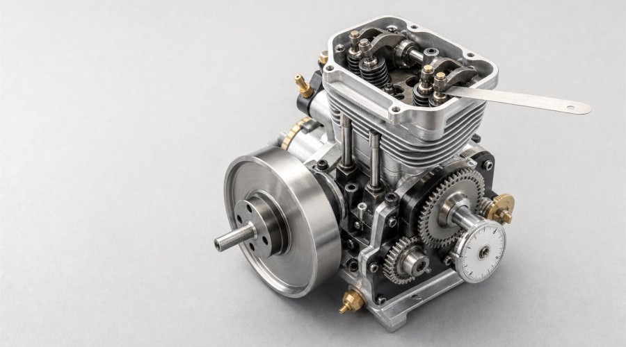
Updated August 1, 2026. This symptom-first guide explains how to verify miniature four-stroke valve timing and lash without guessing at model-specific specifications.
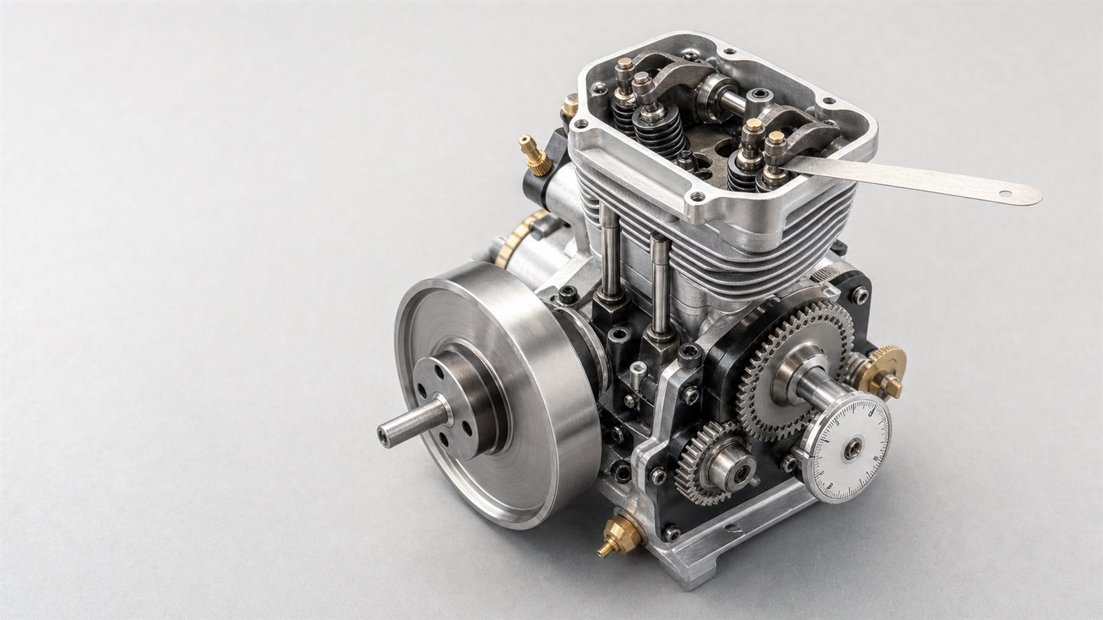
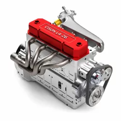
Original EnginesDIY editorial illustration. The generic mechanism supports diagnosis concepts and is not a service diagram for a specific engine model.
Quick answer
If a miniature four-stroke engine will not start, pops through the intake or exhaust, loses compression, kicks backward or becomes difficult to turn after valvetrain work, do not immediately change the carburetor or choose a random valve-clearance number. First obtain the exact manual, confirm top dead center on the compression stroke, rotate the crankshaft through two complete revolutions while observing both valves, verify the timing marks and only then measure lash at the specified temperature and crank position.
Valve timing, valve lash and ignition timing are different variables. A similar symptom can also come from fuel metering, ignition, an automatic compression release, a governor or load mechanism, or poor sealing. The safest diagnosis is therefore a sequence, not a guess.
Important: Manufacturer data controls. This guide explains how to reason about the mechanism; it does not replace the instructions, clearance, direction of rotation or timing-mark procedure for your exact model.
Why the same symptom can point to different faults
A small four-stroke engine has to coordinate piston motion, valve events, mixture preparation and ignition. The crankshaft completes two revolutions for each four-stroke cycle, while the camshaft completes one. NASA's four-stroke explanation shows why this 2:1 relationship matters: the valves must be closed during compression, the intake valve must admit charge at the appropriate part of the intake stroke, and the exhaust valve must release burned gas at the appropriate part of the exhaust stroke.
That coordination creates diagnostic ambiguity. An intake pop may occur because the intake valve is open at the wrong time, because lash is too tight and the valve never fully seats, or because ignition occurs while the intake path is still exposed. Weak compression may reflect a tight valve, a damaged seat, ring leakage, a decompression feature or simply a measurement made under the wrong conditions. A sluggish engine may have incorrect timing, but it may also be rich, overloaded or governed incorrectly.
The practical lesson is simple: treat a symptom as a starting observation, not a verdict.
Three terms that must not be confused
Valve timing
Valve timing describes when each valve begins to open and close relative to crankshaft position. Timing gears, a belt or chain, the cam profile, tappets, pushrods and rockers transmit that relationship to the valves. FAA maintenance material notes that valve events vary by engine and may be specified in crankshaft degrees, so a mark that looks “approximately right” is not a substitute for the correct procedure.
Valve lash or clearance
Valve lash is the specified gap in the valvetrain when the valve should be fully closed and the engine is in the manufacturer's measurement condition. The gap accommodates the design's thermal and mechanical behavior. Too little clearance can prevent full seating; too much can delay effective lift, reduce effective opening and create impact or noise. The acceptable value and whether it is measured hot or cold are model-specific.
Ignition timing
Ignition timing is when the spark occurs relative to piston position. It can create backfire, kickback and poor running that resemble valve faults. Adjusting lash cannot correct a shifted ignition trigger, damaged key, incorrectly installed magnet or unsuitable electronic ignition setting.
Symptom map: what to check first
| Observation | Valvetrain possibilities | Important mimics | First non-destructive check |
|---|---|---|---|
| No start after valve adjustment | Lash set at overlap TDC; valve held open; locknut moved setting | Flooding, dry fuel system, no spark | Remove the plug, hand-rotate two cycles and observe both rockers |
| Pop through intake | Intake closing late; intake valve not seating | Lean mixture, ignition timing | Confirm compression TDC and intake-valve seating before tuning |
| Pop in exhaust | Exhaust event/seat problem | Rich mixture, late ignition, fuel in muffler | Verify exhaust valve closes before compression |
| Low or inconsistent compression | Tight lash; wrong cam phase; valve leakage | Rings, head gasket, decompressor | Compare mechanical cycle, then use compression/leak-down evidence |
| Kickback or reverse impulse | Incorrect phase is possible | Ignition too advanced, prop/flywheel installation | Disable ignition and verify free hand rotation first |
| Loud ticking | Excessive clearance, loose adjuster | Normal gear noise, loose mounting hardware | Inspect locknuts and measure only at the specified position |
| Starts but lacks power | Reduced effective valve event or poor seating | Rich/lean mixture, load, exhaust restriction, governor | Establish timing/lash baseline before carburetor changes |
This table is a triage aid. It does not prove a cause. FAA troubleshooting guidance supports a systematic approach because breathing and performance depend on several interacting conditions.
The T-I-M-E diagnostic sequence
T — Technical data first
Identify the exact engine, revision and valvetrain. Obtain the manufacturer's manual and record:
- normal direction of crankshaft rotation;
- timing-mark definitions and alignment position;
- specified valve-clearance values;
- hot or cold measurement condition;
- whether the piston is exactly at TDC or a stated distance/angle past TDC;
- whether an automatic compression release changes what you will feel;
- locknut torque or tightening method;
- safe starting and lubrication instructions.
O.S. Engines' four-stroke material is a useful example of why this step matters: valve-clearance inspection and readjustment are tied to the particular engine and procedure. Briggs & Stratton technician guidance likewise describes model-specific compression-stroke positioning. Internet numbers borrowed from a different engine may be close enough to seem plausible and still be wrong.
Before touching an adjuster, photograph the existing marks and write down the current clearances. A reversible diagnostic process preserves evidence.
I — Identify compression TDC, not merely “piston at the top”
The piston reaches top dead center twice in a four-stroke cycle: once near the end of compression and once between exhaust and intake events. Lash is commonly checked near compression TDC because both valves are closed, but the exact specified position must still come from the manual.
A practical observation sequence is:
- Disable ignition and fuel. Remove the glow plug or spark plug so the engine can be turned gently.
- Rotate only in the normal direction unless the manual states otherwise.
- Watch the intake rocker. It opens during intake and then returns as the intake valve closes.
- Continue turning as the piston rises. This is the compression stroke; both valves should be commanded closed.
- Locate the specified TDC or after-TDC position with the manufacturer's mark or measuring method.
Do not identify the stroke by piston position alone. Recent owner questions show how easily clearance can be set at the wrong TDC. Also do not force the crankshaft against a stop; unexpected resistance after reassembly is a reason to stop and inspect for interference.
M — Measure lash and map the full mechanical cycle
Use clean, undamaged feeler gauges in the correct thickness range. Insert the gauge in the location described by the manual, normally between the rocker contact and valve stem on an overhead-valve layout. A correct “feel” is a light, consistent drag—not a gauge clamped in place and not a loose blade with no contact.
If adjustment is required:
- Hold the adjuster while loosening its locknut.
- Make a small change.
- Hold the adjuster stationary while tightening the locknut.
- Measure again; tightening often changes the gap.
- Record intake and exhaust values separately.
Then hand-rotate the crankshaft through two full revolutions. Observe intake opening and closing, compression with both valves closed, the power-stroke region and exhaust opening/closing. Confirm that the mechanism moves smoothly, springs return the valves, pushrods remain seated, rockers do not bind and timing marks return to their reference relationship.
This full-cycle map catches errors that a single static measurement misses: a pushrod outside its cup, a gear one tooth out, a loose adjuster, a valve that sticks only at part lift or physical interference near TDC.
E — Eliminate mimics before changing another system
Once mechanical timing and lash match the manual, keep the baseline fixed while testing other causes. Check one system at a time:
- Fuel: correct fuel, fresh supply, appropriate prime, no flooding, clear lines and stable tank height.
- Ignition: reliable spark under the correct conditions, secure trigger/magnet, correct direction and manufacturer timing.
- Compression/sealing: repeatable compression behavior, then a controlled leak-down assessment where appropriate.
- Air and load: unobstructed intake/exhaust, free propeller or driven mechanism, correct governor springs or linkage, no binding accessories.
- Starting technique: correct direction, throttle setting, battery/starter condition and safe restraint.
A recent small-engine community case is instructive: symptoms interpreted as valve or mixture trouble were ultimately caused by incorrect air-vane springs. Community reports are not technical authority, but they illustrate why confirmation bias wastes time.
How to reason about timing marks
Timing marks are assembly references, not universal symbols. Their meaning depends on the manufacturer: dots may mesh together, lines may align with a case surface, or a cam feature may be positioned relative to a crank throw. Never assume that two visible marks should face each other without the correct drawing.
When a cam gear is one tooth out, the engine may still rotate and may even run, but its effective intake and exhaust events shift. NACA/NASA research demonstrates that valve timing affects air capacity and output; on a miniature engine, the practical effects may appear as weak breathing, poor starting, reduced power or abnormal popping. The symptom alone cannot tell you which tooth or direction is wrong.
If the engine was recently disassembled, compare three pieces of evidence: the manual's mark alignment, the observed valve sequence through two crank revolutions, and the compression-stroke position with both valves seated. If those disagree, stop rather than “tuning around” the mechanical error.
Tight lash versus loose lash
Too-tight lash can keep a valve slightly open as components warm or as the mechanism reaches the measurement position. That can reduce sealing and compression and may expose the intake or exhaust path at the wrong moment. It can be deceptively quiet.
Too-loose lash usually creates extra impact and noise and can reduce the effective duration or lift transmitted to the valve. Yet gear trains and small mechanical engines are naturally audible, so sound alone is not a clearance measurement.
The correct answer is not “tight is better” or “loose is safer.” The correct answer is the specified clearance, verified after tightening and after a complete hand-rotated cycle.
A disciplined record sheet
For each diagnostic session, record:
| Field | Entry |
|---|---|
| Engine/model/revision | Exact identification |
| Manual/source | Document title and revision |
| Engine temperature | Cold / warm / specified condition |
| Crank position | Manufacturer-defined reference |
| Intake lash before/after | Measured value and gauge |
| Exhaust lash before/after | Measured value and gauge |
| Timing marks | Photo and stated alignment |
| Two-cycle hand rotation | Smooth / resistance / abnormal event |
| Compression observation | Method and repeatability |
| Fuel/ignition baseline | What was checked without retuning |
| Result after one change | Start, idle, transition, temperature, sound |
Changing one variable and recording the result produces better evidence than making several adjustments and judging by memory.
Safety and stop conditions
- Restrain the engine securely and remove the propeller or driven load when the manufacturer's safe service procedure permits.
- Disable ignition and fuel before hand rotation or valvetrain work.
- Keep tools, clothing and fingers away from rotating assemblies.
- Do not run with exposed gears or rockers unless the manufacturer explicitly provides a safe observation method.
- Stop if the crankshaft binds, a valve contacts the piston, a pushrod bows or leaves its seat, a spring retainer shifts, or an adjuster cannot be locked securely.
- After service, perform the first run at a conservative setting while watching lubrication, temperature, fasteners and abnormal noise.
FAQ
Can I set lash whenever the piston is at top dead center?
No. The piston reaches TDC twice per cycle. Use the manufacturer's specified position, commonly on the compression stroke after the intake valve has closed and while both valves are commanded shut.
Is there one valve-clearance number for all miniature four-strokes?
No. Clearance depends on the engine design, materials, geometry, temperature condition and manufacturer procedure. Use the exact manual.
Does backfire prove the cam timing is wrong?
No. Incorrect valve timing or a valve that does not seat can contribute, but mixture and ignition faults can create similar symptoms. Verify mechanical phase and lash before changing other settings.
Why did the clearance change after I tightened the locknut?
The adjuster can rotate or shift while the locknut is tightened. Hold it as instructed and always remeasure after locking.
Should I tune the carburetor to compensate for weak compression?
No. Establish mechanical integrity first. Carburetor changes can mask one operating point while making starting, transition or temperature worse.
What if the engine has an automatic compression release?
Use the manufacturer's diagnostic procedure. A decompression feature can alter cranking feel and some compression readings, so a generic threshold can mislead.
Conclusion
Miniature four-stroke valve problems are best solved by preserving the order of evidence. Start with exact technical data, identify compression TDC correctly, map two full crank revolutions, measure and remeasure lash, and eliminate fuel, ignition, sealing and load mimics one at a time. This T-I-M-E sequence turns vague symptoms into testable observations while protecting the engine from speculative adjustment.
Continue learning and compare relevant models
After publish-time URL validation, readers can continue with EnginesDIY's miniature four-stroke operating-principle guide, systematic no-start diagnostic guide, model-engine carburetor tuning guide and nitro-versus-gasoline comparison. Relevant products should be explored through Model Engine Kits and Internal Combustion Engine Models, with buying and support details confirmed in the FAQ and shipping information.
References
- O.S. Engines, FS-52S four-stroke engine instructions.
- NASA Glenn Research Center, Four Stroke Internal Combustion Engine.
- NASA Glenn Research Center, Internal Combustion Engine: Otto Cycle.
- FAA, Aviation Maintenance Technician Handbook—Powerplant, Chapter 1 and Chapter 10.
- Briggs & Stratton, Technician Support / Service & Troubleshooting.
- NACA/NASA Technical Reports Server, Effect of Valve Timing on Engine Air Capacity.
- FAA Advisory Circular 20-143.
Related Products
Leave a comment