

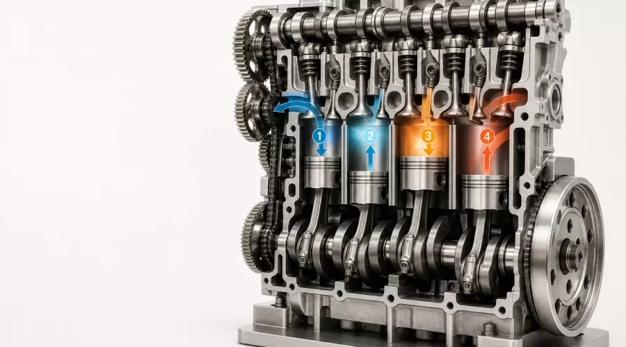
Updated July 21, 2026. A miniature four-stroke engine is not merely a small object that spins. In a working model, the piston, connecting rod, crankshaft, camshaft, valves, ignition, lubrication and cooling systems must stay synchronized through a complete cycle. This visual guide explains what each part is doing, what a model can genuinely demonstrate and what to verify before operating one.
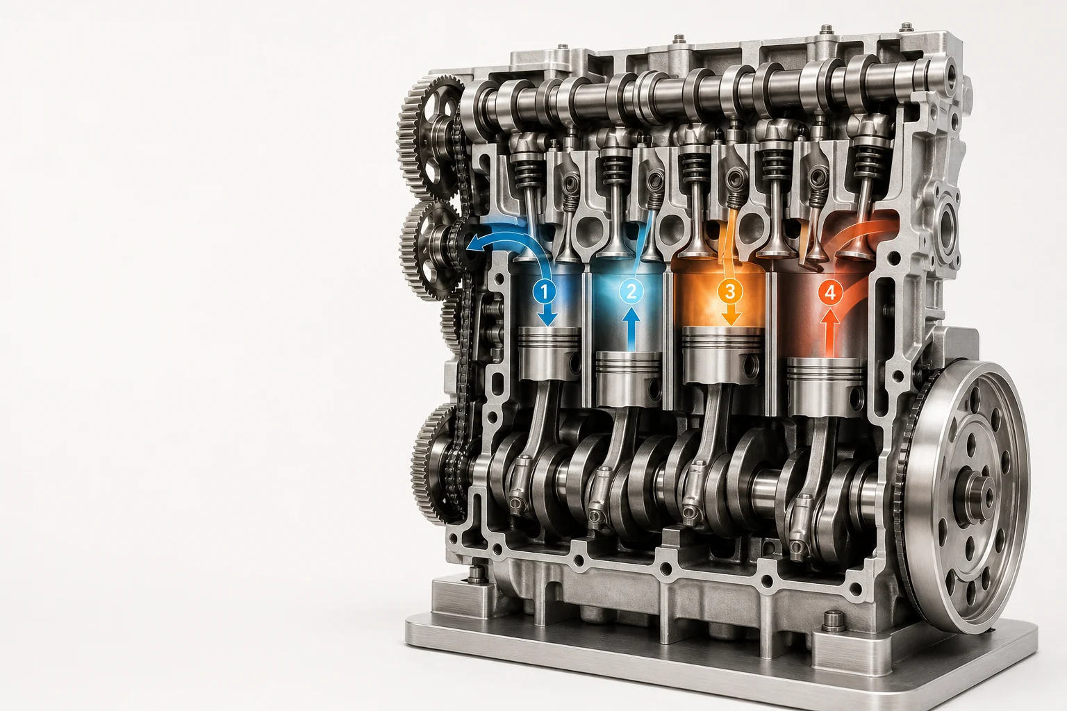
Original EnginesDIY illustration. The four numbered cylinders visualize the four stages of the cycle; a real cylinder completes all four stages in sequence.
Editorial note: EnginesDIY sells working engine models. Engineering statements in this guide are separated from product-selection advice and linked to independent government references. A miniature fuel-burning engine can create heat, moving-part, fire and exhaust hazards. The manual supplied with the exact model—not this article—controls its fuel, lubricant, starting method, adjustments, operating limits and minimum operator age.
Short answer: what happens in a four-stroke engine?
A four-stroke engine completes intake, compression, power and exhaust over four piston strokes and two crankshaft revolutions. During intake, the cylinder fills. During compression, both valves close and the piston reduces the mixture's volume. Near the top of a spark-ignition engine's compression stroke, a spark starts combustion. Expanding gases then push the piston down during the power stroke. Finally, the exhaust valve opens and the rising piston clears the cylinder.
The U.S. Department of Energy's internal-combustion overview describes the same energy path: combustion occurs inside the engine, expanding gases push a piston, and the crank mechanism converts that motion into rotation. A miniature working model uses the same mechanical relationships, but its small scale makes alignment, heat flow, lubrication and fastener condition especially important.
The four strokes, one cylinder at a time
| Stroke | Piston movement | Valve state | What to observe on a model |
|---|---|---|---|
| 1. Intake | Top to bottom | Intake open; exhaust closed | Intake valve lift, piston descent and fuel-air path |
| 2. Compression | Bottom to top | Both closed | Both valves seated and resistance increasing toward top dead center |
| 3. Power | Top to bottom | Both closed | Combustion pressure acting on the piston and accelerating the crankshaft |
| 4. Exhaust | Bottom to top | Exhaust open; intake closed | Exhaust valve lift and spent gases leaving the cylinder |
1. Intake: filling the cylinder
The intake valve opens as the piston moves away from the cylinder head. The growing cylinder volume lowers pressure relative to the intake path, drawing in the charge. On a visible model, watch the intake cam lobe, follower, pushrod or rocker—depending on the valve-train design—and confirm that the valve begins returning to its seat as the piston approaches the bottom of the stroke.
2. Compression: preparing the charge
The intake valve closes and the piston travels upward with both valves seated. The trapped charge occupies a smaller volume, so its pressure and temperature rise. NASA Glenn's four-stroke engine explanation uses the Wright brothers' 1903 engine to show this sequence clearly. If a miniature engine has poor valve sealing, a loose plug or another leakage path, compression will be reduced; that is a mechanical symptom, not a reason to improvise stronger fuel or exceed the manual's starting procedure.
3. Power: converting pressure into torque
In a spark-ignition model, ignition occurs near the end of compression according to the manufacturer's timing specification. Combustion increases cylinder pressure, the piston moves down and the connecting rod turns the crankshaft. Only this stroke adds combustion work to that cylinder's cycle. The flywheel and, in a multi-cylinder engine, the other cylinders help carry the crankshaft through the remaining strokes.
4. Exhaust: clearing the cylinder
The exhaust valve opens and the piston moves upward, sending combustion products through the exhaust port. The valve must then close as the next intake event begins. Hot exhaust components remain a burn hazard after the crankshaft stops. Exhaust composition is also why a fuel-burning model is not an indoor desktop demonstration.
Why the crankshaft turns twice while the camshaft turns once
One complete four-stroke cycle requires 720 degrees of crankshaft rotation. Each valve, however, needs one correctly timed opening event per cycle. A conventional four-stroke camshaft therefore runs at half crankshaft speed, usually through a 2:1 gear, chain or belt relationship. NASA's mechanism notes explicitly point out that the crankshaft makes two revolutions for each cam revolution.
This ratio is one of the most useful checks on a model engine. Turn an unpowered engine slowly by hand only when its manual permits it. Mark the flywheel and cam gear with removable reference points. Two crank revolutions should return the piston and valve train to the same cycle position. Do not change gear mesh or belt position without the model-specific timing marks and manual.
Mechanical cycle versus Otto-cycle diagram
The moving parts are only half the story. The idealized Otto-cycle diagram plots pressure against cylinder volume. NASA Glenn's Otto-cycle thermodynamic analysis explains that work is done on the gas during compression and by the gas during expansion; the enclosed area on an ideal pressure-volume diagram represents net cycle work.
A real miniature engine is not ideal. Heat moves into the cylinder, head, coolant or surrounding air. Gas remains after exhaust. Valves need finite time to open. Friction consumes part of the work. The useful lesson is not that a tiny engine perfectly reproduces an ideal diagram, but that the visible mechanism lets you identify where real losses and timing constraints enter the cycle.
Four systems to trace before choosing a working model
A credible product page should let a buyer identify more than the cylinder count. Trace these four paths in the photos, specifications and manual:
- Gas path: air entry, fuel metering, intake port, cylinder, exhaust port and outlet.
- Motion path: piston, wrist pin, connecting rod, crankshaft, flywheel and any output coupling.
- Timing and ignition path: crank reference, timing gear or belt, camshaft, valve train, trigger and spark system.
- Heat and friction path: lubricant delivery, bearings, cylinder wall, cooling jacket, pump or fins, and the surfaces that remain hot.
The FAA's Aviation Maintenance Technician Handbook chapter on lubrication and cooling is written for aircraft maintenance, not model engines, but it makes the engineering principle clear: lubrication and cooling are complete functional systems. On a miniature engine, the exact oil grade, quantity, cooling medium and priming process remain model-specific.
What changes when an engine is miniaturized?
- Small alignment errors become large relative errors. A slight bearing offset or rubbing rod can consume a meaningful share of the engine's available torque.
- Fasteners and passages are easy to damage or block. Correct tools, clean assembly and the stated tightening sequence matter more than force.
- Thermal conditions change quickly. A small metal assembly can heat rapidly, while its cooling passages and fluid capacity are limited.
- Flywheel inertia is limited. Binding, leakage and incorrect timing can prevent the engine from carrying itself through non-power strokes.
- Settings are not transferable. Needle position, fuel, oil, ignition timing and break-in instructions for one model must not be copied to another.
Working engine, motorized display or cutaway: choose the right learning level
| Type | What moves it | What it can demonstrate | Operating boundary |
|---|---|---|---|
| Hand-turned cutaway | Your hand | Piston-crank geometry and valve sequence | No combustion; check pinch points |
| Electric motorized kit | Small electric motor | Multi-cylinder motion and timing visibility | Not a fuel-burning engine; protect gears and wiring |
| Working fuel engine | Combustion | Starting, ignition, heat, exhaust and load response | Adult operation, exact manual, outdoor use and fire controls |
Start with the intended observation. If the goal is to see valve timing, a cutaway or motorized kit may show more than a closed running engine. If the goal is authentic starting and combustion behavior, choose a working model only when the operator, space, tools and safety controls match the manual.
How current EnginesDIY models map to the mechanism
Browse the internal-combustion engine model collection for different cylinder layouts and valve-train architectures. The following examples are useful comparison points, not interchangeable operating systems:
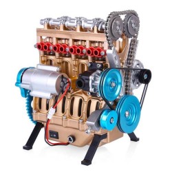
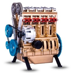
- The TOYAN FS-L400BGC inline four-cylinder engine shows how four pistons share one crankshaft in an inline layout.
- The SEMTO ST-NF2 twin-cylinder model offers a smaller multi-cylinder comparison with a different package and firing arrangement.
- The CISON LS52 V8 engine model illustrates two cylinder banks working through one crankshaft.
- The TOYAN FS-V800 V8 OHV kit is relevant when comparing overhead-valve linkage and a V configuration.
For an earlier stationary-engine architecture with exposed governing behavior, compare the hit-and-miss engine model category. If you are still deciding between combustion, steam, Stirling and motorized mechanisms, begin with the broader model engine kits hub.
Safe operating boundary for fuel-burning miniature engines
Operate a gasoline-powered model outdoors, away from doors, windows and air intakes. CDC/NIOSH warns that carbon monoxide from small gasoline engines can accumulate rapidly, even in spaces that appear ventilated. Its guidance on preventing carbon-monoxide poisoning from small gasoline-powered engines should end the idea that an open window makes indoor running safe.
Use only the fuel and container specified by the manufacturer. OSHA's flammable-liquids requirements emphasize approved containers and control of storage and ignition hazards. For a hobby model, the practical minimum is still strict: no smoking or open flame nearby, no fueling a hot or running engine, immediate spill control, a clear emergency stop method, eye protection, secured loose clothing and bystanders outside the operating area.
- Do not operate indoors, in a garage, basement, vehicle, tent or partially enclosed workshop.
- Do not touch the head, exhaust or cooling system until the manual's cooling period has passed.
- Do not reach across a running flywheel, belt, gear, propeller or output shaft.
- Do not substitute fuel, oil, plug, battery voltage or coolant because another model uses it.
- Stop immediately for a fuel leak, loose part, abnormal knock, loss of cooling flow or uncontrolled speed.
Diagnosis by evidence, not by random adjustment
| Observation | System to inspect | Safe next step |
|---|---|---|
| Hard point during permitted hand rotation | Motion path and alignment | Stop; isolate the binding stage without applying fuel |
| Low or uneven compression | Valve seating, timing and sealing | Compare positions with the manual; do not compensate with fuel |
| Spark present but no start | Cycle timing, charge delivery and model-specific setup | Return settings to the documented baseline |
| Temperature rises unusually fast | Cooling and lubrication paths | Stop, cool fully and verify flow/level exactly as specified |
| New knock, vibration or metal debris | Fasteners, bearings and rotating assembly | Shut down and inspect before another start |
Change one documented variable at a time and record the result. Randomly turning multiple adjustments destroys the evidence needed to identify the fault and can create a second problem.
Frequently asked questions
Does every piston fire once per crankshaft revolution?
No. In a conventional four-stroke engine, one cylinder completes its full cycle over two crankshaft revolutions and has one power stroke during that cycle. Multi-cylinder engines distribute power events among cylinders.
Is a miniature four-stroke engine a real engine?
A fuel-burning model with a cylinder, piston, compression, timed valves, ignition and exhaust is a real internal-combustion engine at reduced scale. A motorized transparent kit is a mechanism demonstrator: valuable for observing motion, but it does not perform combustion.
Why does the camshaft rotate at half crankshaft speed?
The crankshaft turns twice during one four-stroke cycle, while each valve needs one timed event per cycle. The 2:1 drive relationship keeps the cam event synchronized with the correct piston stroke.
Can I run a miniature gasoline engine on a desk near an open window?
No. Fuel-burning engines produce carbon monoxide and hot exhaust. CDC/NIOSH advises against operating gasoline engines inside buildings or partially enclosed areas; apparent ventilation is not a reliable safety control.
What is the best first model for understanding the cycle?
Choose the model that makes the target mechanism visible. A hand-turned cutaway is best for slow valve-timing study; an electric motorized kit adds continuous multi-cylinder motion without combustion; a working fuel engine belongs with an adult operator prepared for its manual, tools, outdoor space and safety requirements.
Editorial methodology
This guide was reviewed against sources from the U.S. Department of Energy, NASA Glenn Research Center, the FAA, OSHA and CDC/NIOSH. Product links illustrate mechanical configurations sold by EnginesDIY. They do not replace product manuals, and no performance, learning or safety outcome is guaranteed. Technical questions about a specific model should include its exact model number and manual revision.
Next step: compare visible mechanisms in the working internal-combustion models, then choose by operating method, manual quality and the system you want to observe—not cylinder count alone.
Related Products
Leave a comment