

Quick answer
There is no single safe break-in schedule for every miniature four-stroke engine. The correct fuel or oil ratio, propeller or load, needle position, RPM ceiling, run duration and valve-check interval must come from the manual for the exact engine. A sound general process is to verify the engine and test stand before starting, use the manufacturer-specified lubricant and conservative initial mixture, monitor speed and behavior with instruments, stop immediately for abnormal heat, noise, binding or lubrication loss, allow controlled inspections between runs, and record each change before leaning or increasing load.
The objective is not to make the engine reach peak power as quickly as possible. It is to let contacting surfaces establish a stable operating relationship while lubrication, cooling, fasteners, valve gear and fuel delivery remain inside the engine maker's limits.
Key conclusions
- Treat the exact manufacturer's manual as the controlling document. Do not copy another engine's numbers because the bore finish, ring design, connecting-rod lubrication, fuel system and materials may differ.
- Separate values from method. RPM, minutes, fuel ratio and needle turns are model-specific; securing the engine, staying outside the propeller arc, checking lubrication and recording observations are broadly useful.
- Use a tachometer when the manual gives an RPM limit. Sound alone is not a reliable speed measurement.
- Do not tune for peak power during the first run unless the exact manual tells you to do so.
- Stop and investigate if the engine tightens, loses lubrication, develops a new metallic noise, sheds hardware, runs uncontrollably, overheats abnormally or shows worsening compression/valve symptoms.
Why break-in exists — and why a universal recipe fails
During early operation, the piston ring and cylinder surface do not behave exactly as they will after a period of controlled running. Peer-reviewed work by MIT researchers models changes in liner surface topography, friction and wear during break-in. That evidence supports a narrow conclusion: break-in is a real tribological transition. It does not prove that every small engine needs the same duration, temperature or load.
The engine maker has information a generic article does not: material pairings, clearances, surface finish, lubrication path and intended fuel. The FAA's guidance on using manufacturer maintenance manuals is written for full-size aviation, but its documentation principle is valuable here: instructions from the maker of the specific equipment are the primary reference. Full-size aircraft limits must never be transplanted into a model engine.
This distinction matters because even two respected model-engine manufacturers publish different procedures. Saito's manual for named four-stroke gasoline engines discusses a specific connecting-rod/crankshaft interface, specifies a tachometer, and gives model-family break-in settings. An O.S. four-stroke manual organizes its own fuel, lubrication, starting, running-in and valve-clearance instructions around that engine. Those are not competing universal truths. They are evidence that the engine identity controls the numbers.
If you are still choosing a powerplant, start with our guide to how a miniature four-stroke engine works, then compare the Internal Combustion Engine Models category. Understanding the valve train, induction and lubrication path makes a break-in manual much easier to interpret.
The three-layer break-in framework
Use three layers instead of one copied recipe.
Layer 1: manual-controlled values
Write these values down before fuel is introduced:
| Item | Where the answer must come from | Why it cannot be guessed |
|---|---|---|
| Fuel type and oil specification | Exact engine manual or verified maker bulletin | Glow and spark engines, and even engine families from one maker, may use different fuels and lubrication systems. |
| Break-in fuel/oil ratio | Exact manual | Extra oil is not automatically safer; an incorrect ratio can change mixture behavior, deposits and lubrication. |
| Propeller, flywheel or test load | Exact manual | Load determines speed, cylinder pressure, cooling and the risk at the rotating assembly. |
| Initial needle positions | Exact manual | Carburetor designs and reference points differ. |
| RPM ceiling or target | Exact manual | Engine sizes, materials and lubrication paths differ. |
| Run duration and progression | Exact manual | Some procedures use staged ground runs; others incorporate later operation under load. |
| Cooling or inspection interval | Exact manual | Requirements depend on construction and the maker's test method. |
| Valve-lash check | Exact manual | Valve gear expands and seats differently; the correct cold/hot condition and clearance are model-specific. |
If the engine has no identifiable manual, the honest status is UNKNOWN. Do not turn a seller's generic listing into an engineering instruction. Confirm the model and obtain the maker's document before running it.
Layer 2: universal pre-run controls
These controls do not replace the manual, but they reduce avoidable errors:
- Identify the engine. Record manufacturer, model, serial or production variant, ignition type and carburetor type. Photograph hose routing and factory settings.
- Turn it by hand only as instructed. With ignition disabled and the plug handled according to the manual, feel for smooth, repeatable rotation. Do not force a tight engine through an unknown obstruction.
- Verify the mount and rotating assembly. A rigid test stand, correct fasteners and the manufacturer-approved propeller or load are essential. Replace any cracked, nicked or unbalanced propeller. The Academy of Model Aeronautics Safety Program Handbook also warns operators to remain outside the propeller arc.
- Check the fuel system. Confirm clean fuel, correct tubing, venting, filter orientation and leak-free connections. Keep ignition components and fuel lines away from heat and rotating parts.
- Prime or pre-lubricate only as specified. Some engines require oil at a particular point before first start; others rely on fuel-borne lubrication. More oil in the wrong place can cause hydraulic lock or contaminate ignition components.
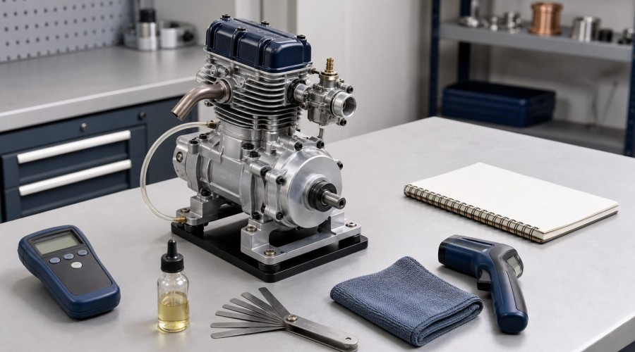
- Prepare instruments. Use a tachometer where RPM is controlled, a suitable temperature instrument if the maker provides a measurement point or limit, and a timer. Instruments support the manual; they do not invent limits.
- Plan a safe stop. Know how ignition or fuel will be cut without reaching through the propeller arc. Never plan to stop the engine with a rag or another object.
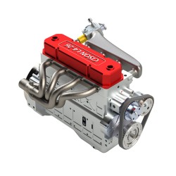
Owners working with multi-cylinder display engines can see how architecture affects access by comparing the CISON L4-175 OHV inline-four with the CISON FL4-175 flathead inline-four. These examples are relevant to layout and inspection access, not a claim that they share one break-in schedule.
Layer 3: observe, stop and decide
A break-in run should be a sequence of controlled observations. Change one variable at a time. If mixture, load and ignition are changed together, you will not know which change caused the result.
Use a log like this:
| Run | Manual setting used | Elapsed time | RPM range | Temperature point/value if specified | Exhaust/smoke | New sound or vibration | Fastener/leak check | Next action |
|---|---|---|---|---|---|---|---|---|
| 1 | Exact starting setting | Stop / repeat / proceed per manual |
The empty cells are deliberate. Enter measured values; never pre-fill a “normal” temperature or speed from another engine.
A manual-first operating sequence
Step 1: read the entire procedure, not one paragraph
Break-in depends on sections that may appear elsewhere in the manual: safety, fuel and lubrication, propeller or load, starting, carburetor adjustment, cooling, valve clearance and after-run care. Reading only the heading called “break-in” can omit a prerequisite.
For example, Saito's documented procedure for its listed gasoline engines ties lubrication requirements, tachometer use and staged settings together. O.S. manuals similarly place running-in beside fuel, starting and mixture instructions. Quote the values into your log with the engine model and manual revision.
Step 2: establish a baseline before the first start
Record compression feel only as a repeatable observation, not a calibrated measurement. Check valve gear where it is accessible and where the manual authorizes inspection. Look for shipping plugs, loose fittings, blocked breathers, pinched fuel tubing or debris.
If valve timing or clearance is already suspect, do not hope break-in will repair it. Use the miniature four-stroke valve timing and lash guide to distinguish a timing/clearance problem from normal early running.
Step 3: start safely and stabilize the manual's initial condition
Secure the engine and keep every person outside the plane of the rotating propeller or flywheel. Use a helper or restraint when the equipment and manual call for it. Start with the maker's initial fuel, ignition and needle settings.
The first goal is not a crisp idle or maximum RPM. It is stable lubrication, controlled speed and predictable response within the documented starting condition. If the engine will not remain running, do not compensate with random needle turns. Work through fuel delivery, ignition, compression and timing using our model-engine no-start diagnostic.
Step 4: measure rather than listen
When the manual gives an RPM maximum, measure RPM. A small engine can sound “comfortable” while running faster than expected, and exhaust note changes with propeller, muffler and surroundings. Hold instruments outside the rotating arc and use them at the specified distance or point.
Temperature is even easier to misuse. An infrared reading depends on surface material, emissivity, distance and the point measured. Unless the maker gives a point and limit, treat temperature as a trend in your own controlled setup, not an absolute pass/fail value copied from the internet.
Step 5: make only the progression the manual permits
Do not lean the mixture, raise RPM, lengthen the run or increase load merely because the engine sounds clean. Follow the exact progression in the manual. If the manual calls for a rich initial setting, understand that “rich” is still a model-specific needle position or observed behavior, not permission to flood the engine.
Final carburetor tuning is a separate task. Once the maker's break-in requirement is complete, use the model-engine carburetor tuning guide to adjust high-speed and transition behavior systematically. Break-in data should not be confused with a final peak-power setting.
Step 6: stop, cool and inspect at planned checkpoints
After each manual-defined stage, stop the engine using the planned control and let it reach the inspection condition specified by the maker. Check:
- mount, muffler and carburetor fasteners;
- fuel, oil and exhaust leakage;
- fuel-line contact with hot or moving parts;
- propeller, spinner, flywheel or coupling condition;
- crankcase breather flow where applicable;
- spark-plug or glow-plug appearance only within the maker's interpretation;
- valve clearance if the manual schedules it;
- new metallic particles in drained lubricant where the design permits inspection;
- compression feel, rotation and valve motion compared with the pre-run baseline.
The FAA Powerplant handbook, Chapter 10 treats inspection as an integral part of engine testing and break-in after overhaul. That full-size context does not dictate miniature-engine values, but it reinforces the method: testing without inspection records discards the evidence needed to catch a developing problem.
When to stop immediately
Stop the run and diagnose before continuing if you observe any of the following:
- a sudden metallic knock, scrape or chirp that was absent at baseline;
- increasing mechanical tightness or failure to rotate smoothly after cooling;
- loss of fuel or lubricant delivery;
- an uncontrolled RPM rise;
- a loose mount, propeller, flywheel, muffler or coupling;
- fuel leakage near ignition or hot exhaust parts;
- a sharp temperature trend outside the maker's limit or a rapid unexplained rise at the same measurement point;
- visible smoke from wiring, bearings or external components rather than normal exhaust;
- worsening valve-train noise, lost compression or irregular valve motion;
- a damaged propeller or rotating part.
Do not “run through” a suspected lubrication or mechanical fault to finish a time target. A timer is not a safety authority.
Common mistakes and the better decision
| Mistake | Why it fails | Better decision |
|---|---|---|
| Copying another model's RPM and minutes | Engine construction and lubrication can differ | Use only values tied to the exact manual and revision |
| Adding extra oil “for safety” | It can alter mixture, combustion and deposits | Use the specified lubricant and ratio |
| Tuning for maximum RPM on the first run | It may defeat a rich or load-limited initial procedure | Complete break-in before final tuning unless the manual says otherwise |
| Judging RPM by sound | Exhaust and propeller change perceived pitch | Use a tachometer |
| Using one infrared temperature number from a forum | Surface and measurement-point differences make it nonportable | Track the maker's specified point/limit or use trend-only data |
| Ignoring fasteners until the final run | Heat and vibration can expose mounting problems early | Inspect at each planned checkpoint |
| Treating all four-strokes as gasoline engines | Glow, spark and lubrication arrangements differ | Confirm the engine and fuel system first |
| Assuming break-in fixes poor timing or valve lash | Mechanical setup faults remain faults | Diagnose and correct the root cause before running |
If fuel-system type is unclear, read nitro versus gasoline model engines. The article explains the operating differences without implying that either fuel has one universal break-in recipe.
What success looks like
A successful break-in is not defined by a dramatic sound change or an advertised power claim. It is defined by completing the manufacturer procedure without abnormal behavior, preserving lubrication and cooling, retaining secure hardware, and establishing repeatable observations that support subsequent tuning and maintenance.
Depending on the design, you may observe smoother rotation, more stable response or changing compression feel. Treat those as observations, not guaranteed benefits. The peer-reviewed tribology evidence explains why contacting surfaces evolve; it does not promise a specific performance increase for a particular miniature engine.
Keep the run log with the manual revision, fuel batch, lubricant, propeller/load and later valve checks. That record becomes useful if the engine develops a starting, tuning or compression problem. For broader product and operating questions, see the EnginesDIY FAQ and browse the complete Model Engine Kits collection.
Frequently asked questions
How long should I break in a miniature four-stroke engine?
Use the duration and progression in the exact engine manual. There is no defensible universal number because procedures vary by manufacturer, engine family, fuel and lubrication design. If the manual cannot be identified, do not substitute a forum number; confirm the engine first.
Should a new model engine be run rich?
Only to the degree and by the method stated in its manual. Many glow and gasoline engine manuals specify an initial mixture strategy, but “rich” is not one portable needle position. Too much fuel can also cause poor combustion or flooding.
Can I break in the engine without a tachometer?
If the manufacturer specifies an RPM ceiling or target, a tachometer is the appropriate way to verify it. Saito explicitly urges tachometer use in its documented gasoline four-stroke procedure. Sound alone is not an RPM measurement.
Do heat cycles apply to every miniature engine?
Do not assume so. Some procedures include staged runs and inspection or cooling intervals, but the length and purpose must come from the exact manual. “Heat-cycle” advice without an engine identity is incomplete.
When should valve lash be checked?
At the interval and temperature condition specified by the manufacturer. Valve clearance can change as parts seat, but checking or adjusting it at the wrong temperature or position can create a new problem.
Can I use a product listing as a break-in manual?
No. A listing may identify fuel or basic specifications, but it rarely contains the complete safety, lubrication, load, starting, adjustment and inspection procedure. Obtain the maker's manual or verified technical bulletin.
Conclusion
The most reliable break-in guide is not a universal set of numbers. It is a disciplined way to apply the exact manufacturer's numbers: identify the engine, document the prescribed fuel, lubrication, load and RPM, secure the test setup, measure instead of guessing, progress only when permitted, and inspect between stages.
That approach respects what the evidence actually shows. Manufacturer manuals control the procedure; independent safety guidance controls the run area; general maintenance sources support inspection and recordkeeping; and tribology research explains why early surface interaction matters. None of them justifies an unsupported shortcut.
References
- Saito / Horizon Hobby, *Owner's Operating Instruction Manual: Saito 4-Stroke Gasoline Engines*: https://assets.horizonhobby.com/on/demandware.static/-/Sites-horizon-master/default/dwf161a5bb/Manuals/Saito_Gas_Engines-Manual.pdf
- O.S. Engines, four-stroke engine instruction manual: https://www.os-engines.co.jp/english/line_up/engine/air/twin/img/manual/36410.pdf
- U.S. FAA, AC 20-77B, *Use of Manufacturers' Maintenance Manuals*: https://www.faa.gov/regulations_policies/advisory_circulars/index.cfm/go/document.information/documentid/1028757
- U.S. FAA, *Aviation Maintenance Technician Handbook — Powerplant, Chapter 10*: https://www.faa.gov/regulationspolicies/handbooksmanuals/aviation/faa-h-8083-32b-chapter-10-engine-maintenance
- Academy of Model Aeronautics, *Safety Program Handbook*: https://www.modelaircraft.org/sites/default/files/documents/100.pdf
- Gu, Wang and Tian, “Modeling the Fatigue Wear of the Cylinder Liner in Internal Combustion Engines during the Break-In Period and Its Impact on Piston Ring Lubrication,” *Lubricants* 7(10), 89: https://doi.org/10.3390/lubricants7100089
*Editorial limitation: this guide explains a verification method. It is not a substitute for the manual supplied with a specific engine, and it does not authorize operation outside local laws, field rules or the maker's limits.*
Related Products
Leave a comment