

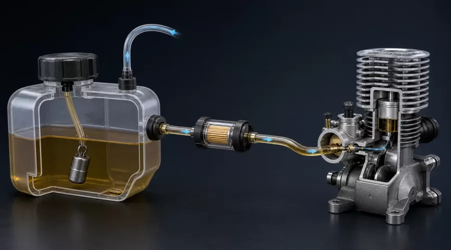
Quick answer: Diagnose a model-engine fuel system as a complete pressure path: tank, pickup or clunk, internal hose, vent or pressure line, external feed line, filter, carburetor and—if fitted—diaphragm pump. First identify whether the system is suction-fed, muffler-pressurized or pump-fed. Then compare tank height and plumbing with the exact engine manual, pressure-test only by the approved method, and observe fuel flow without running the engine lean. Do not correct a plumbing fault by opening the mixture needle indefinitely.
Key principle: Fuel delivery is a pressure path, not just a tube between tank and carburetor. A blockage, leak, wrong height or wrong pressure reference anywhere in that path can imitate a carburetor problem.
What is included in a model-engine fuel system?
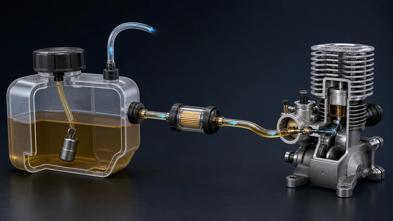
The system begins before fuel reaches the carburetor. A typical tank-fed arrangement contains a sealed or vented tank, a stopper or bulkhead fitting, an internal flexible hose, a weighted pickup called a clunk, a vent or pressure line, an external feed hose, sometimes a filter, and a metering device. A gasoline engine may add a pulse-driven diaphragm pump inside the carburetor. A glow engine may use exhaust pressure at the tank to reduce delivery changes as fuel level and aircraft attitude change.
The FAA powerplant handbook treats fuel-system inspection as a whole-system task: examine for wear, damage and leaks; keep filters and screens clean; and confirm that vents are correctly positioned and unobstructed. Those principles transfer to model systems even though the fittings, pressure and dimensions do not. The exact model manual remains the controlling source.
Use this order when drawing the system:
- Tank pressure reference: open atmosphere, muffler pressure, regulated pressure or a sealed system specified by the manufacturer.
- Pickup: rigid standpipe, moving clunk, filtered clunk or header tank.
- Internal connection: hose length, flexibility, attachment and clearance inside the tank.
- External feed: routing, support, heat exposure, bends and connection security.
- Conditioning: filter, check valve, tee, fill valve or regulator only where documented.
- Metering: suction carburetor, pressure carburetor or diaphragm-pump carburetor.
If any block is unknown, label it unknown rather than guessing. This prevents the common mistake of copying a plumbing diagram from another engine whose carburetor works differently.
Suction-fed, muffler-pressurized and diaphragm-pump systems
| Architecture | What moves fuel | Tank/vent implication | Typical failure |
|---|---|---|---|
| Suction-fed | Low pressure at the carburetor draws fuel from a vented tank | Tank height and distance can strongly affect mixture | Head change, air leak, blocked vent or excessive line loss |
| Muffler-pressurized | Exhaust pressure raises tank pressure while the carburetor meters flow | Vent nipple becomes a pressure connection; sealing matters | Blocked pressure nipple, leaking stopper or disconnected pressure line |
| Diaphragm-pump | Crankcase pulses operate a small pump and metering diaphragm | Usually uses a vented tank, but the exact arrangement is model-specific | Pulse leak, stiff diaphragm, blocked screen or incorrect metering service |
| Regulated/pressurized specialty system | Regulator or dedicated pressure source controls delivery | Requires the named regulator and plumbing instructions | Wrong pressure reference, valve orientation or incompatible component |
O.S. documents this difference clearly. Its MAX-65AX glow-engine manual specifies muffler pressure and a particular tank position relative to the needle valve. Its GT60 gasoline-engine manual states that muffler pressure is not required but an air vent is. These are not contradictory instructions; they describe different systems. Applying the glow layout to the gasoline engine—or leaving the glow tank open when pressure is required—changes the pressure available to move fuel.
Walbro's WY-series technical material describes another architecture. Positive and negative engine pulses actuate a fuel-pump diaphragm, while atmospheric pressure acts on the dry side of a metering diaphragm. The primer purges air and draws fuel into the metering system. A blocked atmospheric vent, pulse leak, damaged diaphragm or inlet-screen restriction therefore cannot be diagnosed reliably by tank height alone.
How should the tank, clunk and vent be installed?
Tank height is a datum, not a universal number
Height matters because liquid creates hydrostatic head. Raise a vented tank relative to a simple carburetor and fuel is easier to deliver; lower it and the carburetor must generate more pressure difference. The result can change as the tank empties or the model changes attitude. But the correct datum may be the needle valve, carburetor centerline or another mark named by the manufacturer.
For example, the O.S. MAX-65AX manual specifies a particular relationship between tank height and needle-valve centerline and tells the installer to keep the tank close to the engine. Saito's official FG-41TS diagram provides its own relationship between fuel level and carburetor. Those figures belong to the named engines. They are evidence that height matters, not a universal chart for every model.
The clunk must follow fuel without sealing itself
A clunk is a weighted pickup on a flexible internal line. In a mobile model it should move toward the available fuel as attitude changes. Its hose must be long enough to reach the useful tank volume but short enough that the weight does not jam at the front, fold the hose or seal flat against the tank wall. O.S. gives a model-specific rear clearance for its installation; use the clearance in your manual rather than copying that number into a different tank.
Before installation, move the tank through expected orientations and listen or observe that the clunk moves freely. After a crash, hard landing or long storage period, recheck it. A stiff internal hose can hold the pickup away from fuel; an overlong hose can kink; a detached hose lets the system draw air above the fuel level.
A vent is part of fuel delivery
Fuel leaving a tank must be replaced by air or by a specified pressure supply. If an open vent is blocked, pressure in the tank falls and delivery can fade. Briggs & Stratton includes a plugged tank vent or screen in official small-engine troubleshooting. The FAA similarly requires fuel vents to be checked for correct position and freedom from obstruction.
In a muffler-pressure system, the line commonly called a vent carries pressure instead of being left open. It must connect to the intended pressure nipple and the tank must seal as designed. A partly blocked muffler nipple, cracked hose or leaking stopper can cause a run that starts normally and then becomes lean as demand rises.
Fuel tubing, filters and connection compatibility
Fuel type determines what the tank stopper, hose, filter, gasket and valve must tolerate. A tube that remains soft in glow fuel may harden, swell or shed material in gasoline, and the reverse assumption is also unsafe. Color alone does not prove compatibility. Use the engine and component makers' material specifications and replace tubing at their interval.
The O.S. GT60 manual specifies gasoline-compatible tubing, periodic replacement, an inline filter and line retainers. Saito likewise calls for gasoline-compatible components in its tank diagram. These supplier instructions apply to their named products; they support the general rule to document material compatibility but do not approve a particular unbranded hose for every fuel.
A filter can protect a small metering passage, but it also adds flow resistance and another pair of leak points. Choose media and area for the required flow and fuel. Install it in the specified direction if it is directional, support its mass, and inspect for trapped debris. Filtering fuel while filling the tank does not remove the need to inspect the engine-side screen or filter.
Keep the feed line as short and direct as the installation allows, without stretching it or allowing contact with exhaust, a cylinder head, sharp edges, gears or a starter. Avoid tight bends that flatten under suction. Secure connections with the approved retainer; do not improvise clamps that cut the hose.
Fuel-starvation, flooding and air-bubble diagnosis
| Observation | Fuel-system possibilities | Other causes | Next safe check |
|---|---|---|---|
| Starts, then leans or stops at high load | Blocked vent/pressure nipple, restricted filter, kinked hose, undersized flow path, pickup uncovering | Lean needle, ignition breakdown, overheating, low compression | Stop; inspect flow path and compare plumbing with the manual |
| Rich upright, lean nose-up | Tank datum, long suction lift, clunk position, internal hose leak | Mixture setting or pump fault | Test attitude with ignition disabled; observe pickup and bubbles |
| Continuous bubbles in feed line | Loose joint, split internal hose, low fuel, pickup above fuel, foaming or cavitation | Transient air after filling | Isolate and leak-check sections using the approved procedure |
| Flooding or hydraulic lock | Tank too high for system, excessive priming, pressure trapped, metering fault, wrong line routing | Needle setting or failed regulator | Disable ignition; follow the manual's flooded-engine clearing procedure |
| Runs cold, stalls hot, restarts later | Heat-soaked line, vapor formation, soft hose collapse, vent restriction, diaphragm degradation | Ignition coil, cooling, clearance or compression change | Record temperature and timing; do not assume vapor lock without evidence |
These symptoms overlap. The model-engine carburetor tuning guide helps distinguish mixture adjustment from delivery failure. The model-engine no-start guide separates fuel from ignition and compression. If a run changes with temperature, also use the cooling and overheating diagnostic instead of assigning every hot stall to fuel vapor.
What do bubbles actually prove?
A moving bubble proves that gas is present in a section of line at that moment. It does not by itself locate the entry point. Gas can enter through a loose fitting, cracked internal tube, exposed pickup or foaming fuel; it can also remain after filling or service. Mark the bubble position, observe whether it grows under priming or cranking, and isolate sections without introducing an unsafe pressure.
Do not tune around a restriction
Opening the high-speed needle may temporarily compensate for reduced pressure or flow, but the margin can disappear when tank level, attitude, temperature or load changes. Establish sound plumbing first, then return to the documented baseline and tune using the manual. A mixture that is safe on the bench is not proof that a mobile model will remain supplied in every attitude.
A controlled fuel-system test workflow
- Make the engine incapable of starting. Disable ignition, glow power and starter according to the manual. Remove stored energy and keep fuel away from hot parts.
- Confirm the architecture. Identify the tank vent or pressure reference, pickup, feed, filter, primer, return and pulse line. Label them physically if several hoses look alike.
- Compare against the current manual. Check tank datum, distance, line material, pressure connection, filter and valve direction. Do not rely on a photo of a similar engine.
- Inspect dry. Look for hardened hose, discoloration, cuts, flattened bends, loose retainers, clogged nipples, contaminated filters and a stuck clunk.
- Check tank movement and seal. Verify the clunk can reach fuel through expected attitudes without touching a wall. Use only the low-pressure leak-test method approved for the tank; excessive pressure can damage it or spray fuel.
- Prime by the documented method. Watch for consistent fuel movement, persistent bubbles and leaks. Do not flood the cylinder.
- Run at the manual's baseline. Secure the model, provide cooling and keep clear of rotating parts. Start rich where specified, then make small documented changes.
- Test one condition at a time. Compare full versus partial tank, low versus high load, and only the safe attitudes permitted by the setup. Record fuel level, temperature and symptom onset.
- Stop at warning signs. A sudden lean surge, loss of fuel flow, overheating, hydraulic lock or loose line requires shutdown and inspection—not another needle turn.
If the engine has been stored, review the model-engine lubrication guide before forcing rotation. A stuck ring, gummy preservative or corroded bearing can mimic fuel-system load. For weak fuel draw associated with mechanical condition, the compression and leak-down guide provides a separate evidence path.
Fuel-system component selection checklist
For parts in the engine mounts, fuel and exhaust systems collection, confirm all of the following before purchase:
- fuel chemistry and oil-content compatibility;
- inside/outside diameter and barb fit;
- required flow at full load, not only idle;
- tank capacity and permitted mounting orientation;
- vent, pressure, fill and return arrangement;
- clunk mass, filter media and internal-hose flexibility;
- carburetor type and whether it contains a diaphragm pump;
- temperature, vibration and replacement interval;
- manufacturer documentation for every valve or regulator.
A small nitro RC engine, a single-cylinder gasoline model and a miniature inline-four gasoline engine can all use a tank and hose, yet their fuel, metering and installation requirements differ. Verify the specific product manual and supplied carburetor rather than selecting by displacement or appearance.
Facts, inferences, unknowns and safety limits
- Fact: an unobstructed vent or correct pressure reference is necessary for the system designed around it; leaks and restrictions can affect fuel delivery.
- Reasonable inference: mapping pressure and flow before tuning reduces the chance of misdiagnosing plumbing as a needle problem.
- Supplier instruction: tank height, pickup clearance, tubing type, pressure connection, filter and replacement interval apply only to the named engine/manual.
- Unknown without testing: where a bubble entered, whether a hot stall is vapor lock, or whether an unmarked hose is compatible.
Model fuel is flammable and its vapor can ignite. Work in appropriate ventilation, keep ignition sources away, wear eye protection, secure the engine and keep hands, tools and clothing away from a propeller, flywheel, belt or starter. Never pressurize a tank by mouth, use oxygen, exceed the maker's test pressure or clear a line toward your face. Wipe spills, isolate batteries and allow hot components to cool before refueling.
If liquid fuel may be trapped in the cylinder, do not energize the starter. Follow the engine's flooded-engine procedure with ignition disabled and the model positioned safely. Incompressible liquid can create hydraulic lock and damage a connecting rod, starter or gear train.
Frequently asked questions
Should a model-engine fuel tank be level with the carburetor?
Use the exact engine manual. Some manuals reference the needle valve, others the carburetor centerline or a specified fuel level. Pumped systems can have different limits. There is no universal level that is safe for every model engine.
How long should the clunk line be?
Long enough for the pickup to follow fuel through intended attitudes, but short enough that it cannot jam, fold or seal against the tank wall. Use the tank or engine maker's clearance and test movement before installation.
Does every glow engine need muffler pressure?
No. Some glow-engine manuals specify it, while other carburetor systems use suction, a pump or a regulator. Connect pressure only when the engine's plumbing diagram calls for it.
Why are there bubbles in the fuel line?
Possible causes include a loose fitting, split internal hose, exposed pickup, low fuel, foaming, heat or residual air after filling. A bubble is evidence of gas in the line, not proof of one specific failure.
Can I use the same silicone tube for gasoline and glow fuel?
Only if the tubing manufacturer approves it for the exact fuel and oil blend. Use documented gasoline-compatible tubing for gasoline systems; do not infer compatibility from color or softness.
Why does the engine run well with a full tank but lean out later?
Fuel-head change, a blocked vent or pressure line, pickup exposure, filter restriction, an air leak or inadequate pump delivery are possibilities. Inspect the whole path before altering the mixture.
Conclusion
A reliable model-engine fuel diagnosis begins with architecture. Identify what creates pressure difference, map every component, follow the model-specific tank and tubing instructions, and test the path before tuning the carburetor. When evidence is missing, preserve the unknown and obtain the manual. That discipline is safer—and usually faster—than compensating for a delivery fault with a richer needle.
References
- FAA Aviation Maintenance Technician Handbook—Powerplant, Chapter 2
- O.S. Engines MAX-65AX W/E-4010A Instruction Manual
- O.S. Engines GT60 Instruction Manual
- Saito FG-41TS Instruction Manual
- Briggs & Stratton Small-Engine Troubleshooting
- Walbro WY-Series Carburetor Operating Functions
- Academy of Model Aeronautics: The Mystery of Muffler Pressure
- To compare operating methods and assembly levels after diagnosis, browse model engine kits.
Leave a comment