
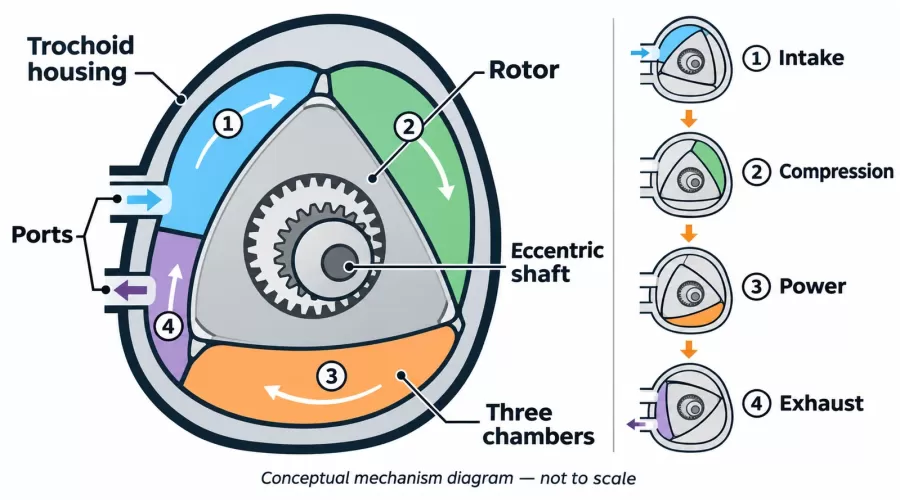
Quick answer: A Wankel engine makes power with a triangular rotor moving eccentrically inside a shaped housing. The rotor and housing form three chambers whose volumes change as the rotor moves. Ports let each chamber pass through intake, compression, combustion and exhaust. An eccentric shaft converts the gas force into output rotation, while a phasing gear set controls rotor orientation. The gears are not a substitute for the shaft as the engine’s torque path.
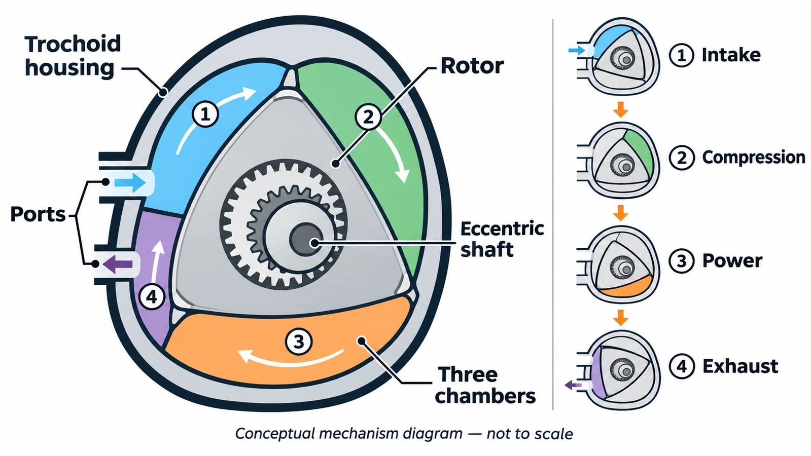
A Wankel cutaway can look deceptively simple: one triangular rotor, one curved housing and a shaft through the middle. The challenge is understanding how those shapes make several sealed spaces change size without a piston moving up and down. Once you can trace one chamber, the ports, eccentric shaft and phasing gears become much easier to read.
Three moving chambers share one rotor, but only the cutaway tells you which parts are visible. That distinction matters: a simplified simulation can make motion understandable without representing every seal, port, cooling path or operating system in a combustion engine.
This guide follows the mechanism rather than prescribing a repair or operating procedure. It explains what a Wankel animation or educational cutaway can show, what it cannot prove about a real engine, and how the rotary cycle differs from a conventional piston engine. The examples are general mechanism principles—not dimensions, performance data or service instructions for any specific model.
Key takeaways
- The rotor’s three faces and the housing create three working chambers; the chambers change volume as the rotor moves.
- Each chamber passes the intake, compression, combustion and exhaust regions. These phases overlap because different chambers are at different points in the cycle at the same time.
- The rotor moves eccentrically around the output shaft. Combustion pressure acting on a rotor face creates force that the eccentric converts into shaft torque.
- The phasing gears guide the rotor’s orientation. They are timing/positioning elements, not the primary path that carries combustion torque to the output shaft.
- A cutaway simulation can help explain visible geometry, but it cannot establish fuel capability, compression sealing, power, durability or safe operation.
The parts to identify in a Wankel cutaway
Rotor: The roughly triangular rotating element has three faces and three corner regions. Each face borders a working chamber. It is not a piston: it does not travel in a cylinder or reverse direction at the ends of a stroke.
Housing: The inner housing surface follows a trochoidal profile, commonly described as epitrochoidal in the standard geometry. That carefully shaped boundary lets the rotor maintain separated chamber spaces while moving eccentrically. It is not simply an oval hole. The housing and side plates also carry the ports and close the sides of the chambers.
Chambers and seals: The three spaces lie between the rotor faces and the housing/side surfaces. Apex seals at the rotor corners and side seals help separate neighboring spaces. A real combustion engine depends on the designed sealing system, clearances, materials, lubrication and thermal behavior. A solid educational model may show the chamber boundaries without reproducing a working gas seal.
Eccentric shaft: The shaft has an offset journal, or eccentric, that supports the rotor away from the shaft’s centerline. As a chamber’s gas pressure pushes on a rotor face, the offset geometry creates a moment about the shaft. This is the useful output path. A model with a freely turning rotor may expose the motion, but visible rotation alone does not measure torque or prove an engine can combust fuel.
Phasing gears: A fixed gear and a gear associated with the rotor constrain how the rotor is oriented as it travels around the eccentric. They keep the geometry synchronized with the housing and ports. In an explanatory cutaway, think of them as guides that preserve phase. Do not infer a particular tooth count or transmission ratio unless the exact engine documentation supplies it. For a separate introduction to general gear trains, see the miniature-engine gear-ratio guide.
Ports: Intake and exhaust openings are placed in the housing or side plates, depending on the engine’s design. As a chamber travels past them, its connection to the intake, combustion zone or exhaust changes. Port location and timing are design-specific; a generic diagram cannot determine the port map of an exact engine.
Why one rotor makes three changing chambers
Look at the three spaces between the rotor and housing rather than treating the rotor as one solid “piston.” As the eccentric shaft turns, the rotor center follows an offset path. At the same time, the rotor changes its orientation relative to the housing. The trochoidal inner wall and the rotor’s three corner seals keep the three spaces distinct while their volumes expand and contract.
At any instant, one chamber may be growing near an intake port, another may be shrinking during compression, and a third may be expanding after combustion or moving toward exhaust. The phases are not four separate moves of the whole rotor. They are changes experienced by each chamber as it passes around the housing. A diagram that colors all three spaces differently is showing simultaneous chamber states, not three separate engines.
The University of California engineering thesis in the source list describes the changing chamber volumes and the rotor’s eccentric placement. NASA’s technical account likewise explains how combustion pressure acts away from the mainshaft centerline and why the eccentric bearing supplies leverage. Mazda’s overview provides manufacturer context for the triangular rotor’s rotational motion. These sources support the conceptual mechanism; none is a miniature-model specification.
The visible phasing gear pair may invite a gear-train calculation, but that is not the main task when learning the cycle. For a first read, ask only: which component is fixed to the housing, which moves with the rotor, and how does their engagement keep the rotor facing the right way as the eccentric carries it around? Exact gear geometry varies by design. The gear engagement controls orientation; the eccentric shaft is where useful output torque is delivered.
Follow one chamber through intake, compression, power and exhaust
Choose one rotor face and the chamber adjacent to it. Follow that chamber around the housing rather than jumping between the three spaces. The exact port layout and ignition arrangement vary, but the familiar four processes provide a useful map:
- Intake: As the chamber grows and passes the intake opening, fresh charge can enter in a combustion engine. The actual induction path, fuel preparation and port arrangement belong to the exact engine design.
- Compression: The chamber’s volume decreases after it leaves the intake region. The trapped charge is compressed before ignition. The seals and side surfaces must keep adjacent chambers separated for a real engine to work.
- Combustion and expansion: Ignition raises pressure. The expanding gas pushes on a rotor face. Because the force acts through the eccentric geometry, it contributes to output-shaft torque and advances the mechanism.
- Exhaust: As the chamber reaches the exhaust opening, spent gas can leave. Continued movement reduces the remaining volume and brings that chamber back toward the intake portion of its path.
While that one chamber is in one phase, the other two are in different phases. This is why a Wankel animation often shows several colored regions at once. The engine’s timing is continuous in the mechanical sense: port exposure and chamber volume evolve with rotor position. An animation can make this easier to see than a static cutaway, but animation timing is not a measurement of a real engine’s speed or combustion quality.
A useful contrast is a four-stroke piston engine. Its piston reverses direction and a crankshaft converts reciprocating motion. A Wankel’s rotor both rotates and travels eccentrically; it does not have conventional pistons, connecting rods or poppet valves in the same arrangement. Both can follow the Otto-cycle sequence, but the moving geometry and sealing challenges are different. For the piston-based mechanism, compare our four-stroke engine-cycle explainer and model-engine compression guide.
How combustion force reaches the output shaft
It is easy to assume that the gears visible in a rotary-engine cutaway transmit all the engine’s torque. That is not the right mental model. Combustion pressure loads a rotor face. The rotor is supported on the eccentric shaft, and the offset between the pressure force and shaft center produces a turning moment. The phasing gears constrain the rotor’s orientation as the parts move, while the shaft carries the useful output.
The basic physical idea is similar to a lever: a force applied away from a pivot can create torque. In the Wankel, however, the moving contact, pressure distribution, chamber geometry, bearings, seals and structural loads are all part of a designed system. The lever analogy explains direction, not actual torque magnitude. Without force, geometry, speed and measurement data, a cutaway cannot provide a power figure.
Real engine implementations also include parts that an educational model may omit or simplify: side housings, bearings, seals, lubrication passages, cooling paths, ignition components, intake and exhaust systems, and accessory drives. The Austro Engine manual is a useful example of a real single-rotor aircraft engine with model-specific cooling and installation systems. Its values and instructions apply only to that engine and are not instructions for a desktop model.
A practical checklist for reading a Wankel diagram
| Start with | Question to ask | What the view can establish | What it cannot establish alone |
|---|---|---|---|
| One rotor face | Which changing chamber touches this face? | Where one chamber sits in the illustrated mechanism | Actual compression, sealing or combustion |
| Housing profile | How does the wall boundary shape the chamber? | Why chamber volume changes as the rotor moves | Exact dimensions or manufacturing tolerance |
| Ports | Which opening can the chamber reach next? | Intended flow sequence in the drawing | Exact port timing on an undocumented engine |
| Eccentric shaft | Where is the rotor supported off-center? | How chamber pressure can create a shaft moment | Torque, RPM or output power |
| Phasing gears | Which gear is fixed, and what does engagement constrain? | How rotor orientation is maintained | That the gear pair is the output torque path or a universal ratio |
| Seals and side plates | How are neighboring chambers separated? | Where sealing interfaces are intended to be | Leak rate, durability, temperature limits or service condition |
A useful sequence is to identify the housing, mark one rotor face, outline its adjacent chamber, locate intake and exhaust openings, and then trace how the eccentric carries the rotor. Only after that should you observe the other two chambers. If the illustration is exploded, determine which faces close the chamber sides. If an animation does not label the shaft, fixed gear or ports, do not assume their position from a different engine’s image.
This “one chamber at a time” method is also useful when comparing an internal-combustion Wankel with a mechanical simulation. EnginesDIY’s Full-Metal Wankel Rotary Engine Cutaway Model is described on its product page as an educational mechanical simulation rather than a fuel engine. That distinction matters: the model can illustrate visible rotor and shaft motion without reproducing the complete combustion, sealing, cooling, lubrication or control systems of an operating engine.
What a mechanical Wankel model can demonstrate
A moving cutaway can help learners see that a rotor face bounds a changing chamber, that three chamber spaces coexist, and that the rotor is carried eccentrically. Depending on the exact model and which parts are exposed, it may also show ports, gears or the output shaft. Those are observable mechanical relationships, not performance claims.
Before choosing any educational model, read the exact listing’s description, selected version, gallery and package contents. Do not assume that “rotary engine model” means fuel-powered, self-running or suitable for RC installation. The Wankel listing above explicitly describes a simulation model. Other model categories may represent working combustion, steam, Stirling or turbine mechanisms; compare those distinct architectures in our model-engine kits collection, internal-combustion models and steam-engine models.
Also separate an illustration’s visible geometry from the specifications a buyer needs. A rendering may omit small parts, simplify internal surfaces, or show a cutaway that is not a literal section through the item. Use the product’s own current photographs and specification table to evaluate the offered model. If a listing does not say whether a part moves, what supplies power, or what is included, ask the seller rather than inferring it from a generic Wankel diagram.
Limits and safety
This article is an educational explanation, not an engine service manual, ignition guide, assembly procedure, or permission to operate a rotary engine. A real fuel engine can contain hot surfaces, moving parts, fuel, electrical ignition and high rotational energy. Use the exact manufacturer’s current manual, suitable guarding and a controlled workspace. Do not open, energize, fuel, or test an engine based on a cutaway animation or this general explanation.
Likewise, do not dismantle a model to discover its mechanism if its instructions prohibit it or if disassembly could damage the item. A diagram is not evidence of material, tolerances, durability, certification, measured output or a safe operating limit. Manufacturer manuals cited here concern their named engines; they are included to explain how real rotary systems are documented, not to transfer their procedures to a miniature product.
Frequently asked questions
Does a Wankel engine have pistons?
No conventional reciprocating pistons are used in the standard Wankel arrangement. A roughly triangular rotor moves eccentrically within a shaped housing and forms three changing working chambers.
Why are there three chambers?
The rotor has three faces. Each face borders a chamber between the rotor and housing, so three separate chamber volumes change as the rotor moves. At one moment they can be in different phases.
What does the eccentric shaft do?
It supports the rotor off-center. Pressure on a rotor face can then create a turning moment about the output shaft. The exact force and output depend on the complete engine design and measurements.
Do the Wankel gears transmit the engine’s output torque?
The phasing gears constrain rotor orientation. The useful combustion torque is transmitted through the rotor’s eccentric support to the output shaft. Do not infer a specific gear ratio or design from a generic illustration.
Is a Wankel cutaway model a working fuel engine?
Not necessarily. Check the exact product description. The EnginesDIY Wankel cutaway listing identifies its item as an educational mechanical simulation, not a fuel engine.
Can a cutaway tell me the engine’s power or compression?
No. It shows geometry, not measured torque, speed, compression sealing or combustion. Those require appropriate model-specific instrumentation and evidence.
Can I use an aircraft Wankel manual to service a desktop model?
No. Manufacturer instructions, limits, fluids, installation and maintenance are specific to the named engine. Follow the exact manual supplied for the model, if it is an operating engine.
Conclusion
To understand a Wankel rotary engine, trace one rotor face, the chamber beside it, the ports it passes, and the eccentric shaft that receives the force. The three chambers change volume together but occupy different cycle phases. Phasing gears keep the rotor oriented; the eccentric shaft is the output path. A cutaway makes those relationships visible, while product documentation—not a generic diagram—must answer questions about a specific model’s function, configuration and limits.
References
- Mazda Newsroom: Rotary Engine.
- NASA Technical Reports Server: Rotary Combustion Engine background and basic operation.
- NASA Technical Memorandum 2010-216353: Rotary Engine Friction Power.
- University of California eScholarship: Wankel rotary-engine design thesis.
- Austro Engine: AE50R/AE50RA/AE50RAB Engine Manual, Revision 6.
- Fichtel & Sachs: Wankel Repair Manual No. 4010.8 E/2.
- Mazda Newsroom: Rotary Engine Vehicle Production Milestone (2023).
Leave a comment