

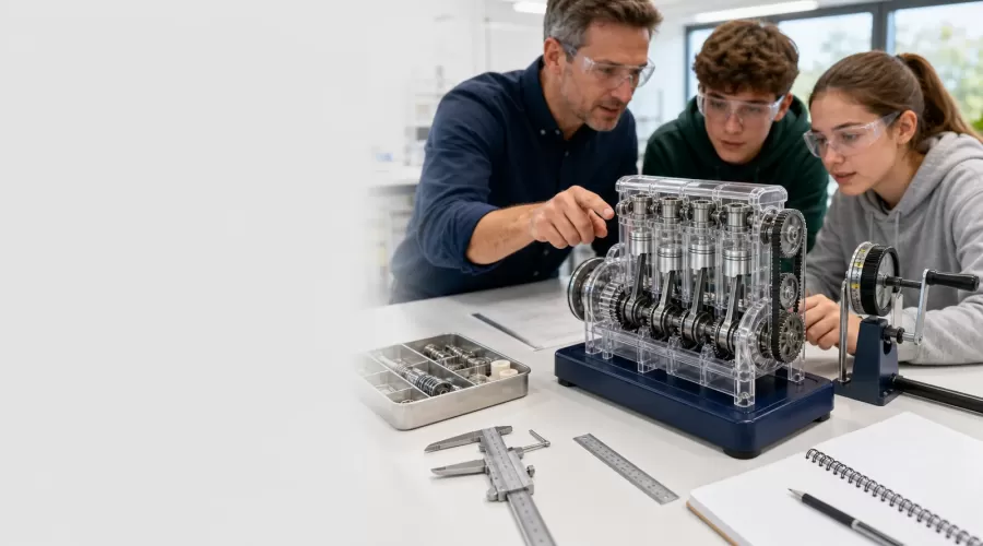
Updated July 2026. Building an engine model becomes a strong STEM activity when the learner does more than follow an assembly sequence. The learner should ask a question, make a prediction, observe or measure the mechanism, explain the evidence, and change one variable. The five projects below can be adapted for home, makerspace, or secondary-school use.
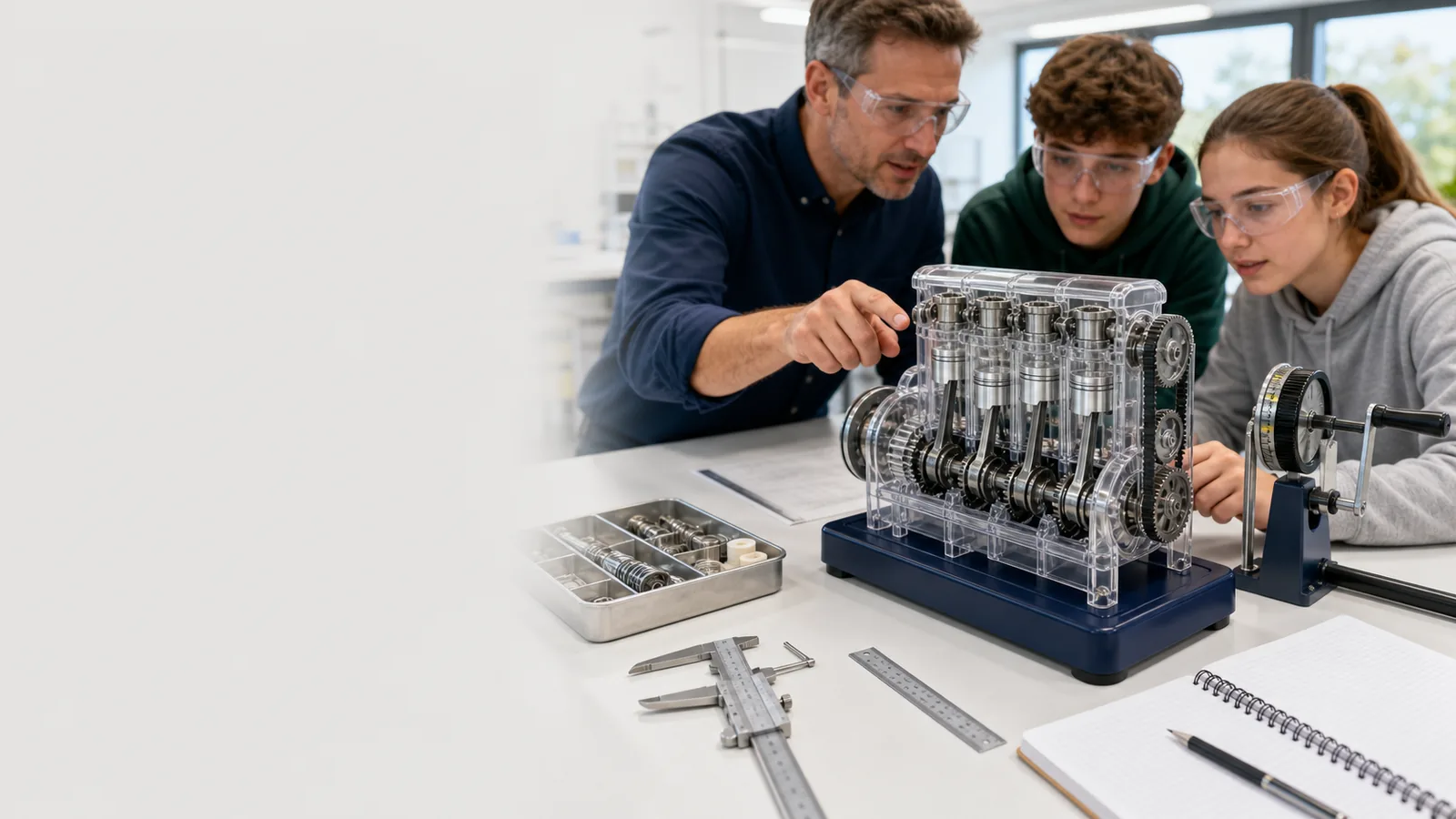
Editorial and safety note: EnginesDIY sells engine models. These activities use hand-turned or low-voltage demonstration mechanisms unless a product manual explicitly permits another method. A teacher or parent must follow the product's age guidance and identify small parts, tools, pinch points, heat, pressure, electricity, and fuel hazards before the session. Do not use live steam or a combustion engine for a general classroom activity.
The learning model: observe, measure, explain, refine
The National Academies lists practices such as developing and using models, planning investigations, analyzing data, using mathematics, designing solutions, and communicating information in its Framework for K-12 Science Education summary. Its investigation and design resources emphasize that students should make sense of phenomena and look for solutions, not just complete a prescribed task.
A U.S. National Science Foundation-supported program similarly asked students to define an engineering problem, construct a prototype, collect data, and change the design based on evidence. The NSF project description is useful because it treats making as a reasoned cycle rather than a craft exercise.
Before class: choose the model and set boundaries
- Select a hand-turned or low-voltage model with visible motion.
- Confirm the manufacturer's age guidance and required supervision.
- Inventory parts and remove any activity that requires heat, pressure, fuel, or a sharp tool beyond the group's capability.
- Prepare safety glasses, parts trays, ruler, stopwatch, paper, pencil, and a copy of the manual.
- Test the model yourself and identify the correct shutdown or disconnect method.
- Assign roles: operator, observer, recorder, and safety checker. Rotate roles after each trial.
The CPSC recommends following package age guidance and keeping small parts away from children younger than three. See its toy safety guidance. A detailed metal engine kit may be general hobby equipment rather than a children's toy, so the product label and manual control the decision.
Project 1: map the four-stroke sequence
Best model: transparent or open piston engine that can be rotated slowly by hand.
Question: How do piston position and valve state change during one complete four-stroke cycle?
- Mark a reference point on the flywheel or crank without altering the model.
- Rotate slowly and stop at intake, compression, power, and exhaust positions.
- For each position, record piston direction and which valve appears open.
- Count crankshaft revolutions required for one complete sequence.
- Draw a four-box diagram and explain where gas would enter and leave a real engine.
Evidence check: The learner should distinguish visible mechanical motion from actual combustion. NASA's Otto-cycle explanation provides the reference sequence and notes that a real cycle includes losses absent from the ideal model.
Catalog starting point: compare the V8 STEM working engine model kit and other products in model engine kits. Confirm the operating method on the exact page.
Project 2: measure crank motion and piston stroke
Best model: open crankshaft model with an accessible piston or connecting rod.
Question: How does constant crank rotation produce changing piston speed?
- Divide one crank revolution into eight equal angular positions.
- At each position, measure a safe external reference point linked to piston position. Do not place a ruler inside a moving mechanism.
- Plot position against crank angle.
- Identify where position changes most and least between steps.
- Explain why the piston momentarily changes direction at the ends of its stroke.
Extension: Compare two cylinders on a multi-cylinder model. Record whether their piston peaks occur together or at different crank angles. Relate the observation to smoother torque delivery without claiming a firing order the model does not document.
Project 3: friction and alignment investigation
Best model: partly assembled kit where a shaft can be tested before and after linkages are connected.
Question: Which assembly stage adds the most resistance, and can alignment reduce it?
- Before adding the next subassembly, give the flywheel the same gentle hand input and count free rotations.
- Install one component according to the manual.
- Repeat the test three times and record the average.
- If resistance rises unexpectedly, inspect parallel supports, rubbing rods, collar spacing, and fastener sequence.
- Change one allowed alignment variable, repeat the test, and document the result.
Control rule: Do not add extra lubricant or loosen safety-critical fasteners simply to improve the number. Use only maker-approved adjustments. The learning target is fair testing: same input, one variable changed, repeated observations.
Project 4: compare piston and turbine engines
Best models: one hand-turned piston model and one turbofan or turboprop cutaway.
Question: Which components perform compression, energy addition, and power extraction in each architecture?
| Function | Piston model | Gas-turbine cutaway |
|---|---|---|
| Admit or move air | Intake valve and piston motion | Inlet, fan and compressor stages |
| Compress | Piston reduces cylinder volume | Rotating compressor stages raise pressure |
| Represent energy addition | Power-stroke stage in the cycle | Combustor section in the flow path |
| Extract or transmit work | Piston, rod and crankshaft | Turbine stages and shafts |
| Exhaust | Exhaust valve and piston | Turbine exit and nozzle path |
NASA Glenn states that gas turbines share a compressor, combustion section, and power turbine. Use its gas turbine propulsion guide to verify the labels. Then inspect the turbofan and jet engine kits and ask which parts are structural representations and which parts actually move.
Project 5: design a maintenance and inspection card
Best model: any completed model with a clear manual.
Question: What evidence would show that the model is ready for another safe demonstration?
- List every rotating, sliding, electrical, heated, or pressurized area present on the exact model.
- For each area, copy the relevant maker instruction in your own words without changing its limit.
- Create a pre-run check, a stop condition, and a post-run check.
- Add a space for date, inspector, observation, and corrective action.
- Ask another group to use the card. Revise any line they interpret differently than intended.
This project teaches technical communication and human-centered design. A checklist is successful only when another person can use it correctly. The National Academies identifies communicating information and designing solutions as core engineering practices; this activity applies both to a real maintenance need.
Student data sheet
| Field | Student entry |
|---|---|
| Question | What are we trying to find out? |
| Prediction | What do we expect, and why? |
| Variables | What changes, what is measured, and what stays the same? |
| Procedure | Numbered steps another group can repeat |
| Observations | Measurements, sketches, unexpected sounds or motion |
| Claim | One answer to the question |
| Evidence | The observations that support the claim |
| Revision | What we would change in the model, test, or explanation |
Simple assessment rubric
| Criterion | Beginning | Developing | Strong evidence |
|---|---|---|---|
| Mechanism explanation | Names parts | Describes a motion link | Traces input, transformation and output |
| Measurement | Records one value | Repeats with units | Uses repeated trials and explains variation |
| Safety | Needs reminders | Follows the checklist | Identifies a new hazard and proposes a valid control |
| Reasoning | Gives an opinion | Uses one observation | Connects multiple observations to a clear claim |
| Revision | No change proposed | Changes several things at once | Changes one variable and retests |
Common teaching mistakes
- Finishing becomes the only goal. Pause after each subassembly for prediction and explanation.
- The adult fixes every problem. Ask the learner to locate the first point where motion changes.
- More power is used to overcome binding. Disconnect the power and correct alignment instead.
- A model is treated as a perfect copy. Identify what the model simplifies or leaves out.
- One trial becomes a conclusion. Repeat measurements and discuss variation.
- Safety is presented as a warning after the activity. Make hazard identification part of the engineering task from the start.
Frequently asked questions
Do students need to assemble the whole kit?
No. A teacher can preassemble hazardous or time-consuming sections and let students investigate one visible mechanism. Learning depends on the question and evidence, not on owning every assembly step.
Can these projects use a running gasoline engine?
Not as a general classroom activity. Fuel, ignition, exhaust, heat, rotating parts, noise, and shutdown procedures require specialist facilities and competent operators. Use a hand-turned cutaway to teach the cycle.
What if the model does not work?
A non-working model can support a valuable diagnosis if power is disconnected and the group checks alignment, interference, timing, and part orientation methodically. Never increase pressure, voltage, or heat beyond the manual to force a result.
How do I avoid an activity that is only entertainment?
Require a written question, prediction, measurement table, evidence-based claim, and one revision. Those five elements make the learner's reasoning visible.
Next step: select a hand-turned or low-voltage product from model engine kits, choose one project above, and prepare the data sheet before opening the parts.
6 Comment(s)
1
1
1
1
1
1
1
1
1
1
1
1
1
1
1
1
1
Leave a comment