

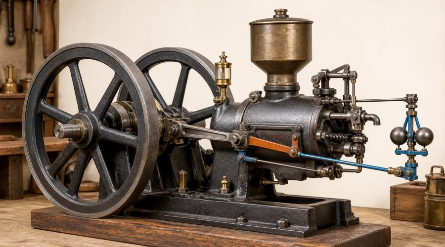
Updated August 5, 2026. A hit-and-miss engine can look almost idle and then suddenly fire. That is not random behavior. It is the visible result of a mechanical feedback loop: rotating flyweights sense speed, a spring and linkage establish a switching point, a latch interrupts selected power cycles, and the flywheels carry the load while the engine coasts.
Quick answer
A hit-and-miss governor does not normally meter the fuel smoothly on every cycle. When engine speed rises above its governing point, centrifugal flyweights move a collar or lever that lets a latch hold part of the valve or fuel-control mechanism in the “miss” position. On many classic designs, the exhaust valve is held open. The cylinder then cannot retain a normal fresh charge, so no power stroke occurs. As the flywheels and load slow the engine, the weights move inward, the latch releases, and the engine resumes one or more firing cycles.
The exact linkage varies. Some engines interrupt the exhaust-valve motion; others act on a gas or fuel valve. That difference matters when identifying a model or diagnosing a fault. The reliable way to understand any example is to follow four functions in order: speed sensing, threshold decision, cycle interruption, and flywheel energy storage.
Key findings
- The flyweights are the speed sensor, not the part that powers the engine.
- The spring preload and linkage geometry determine when the governor changes state; they do not guarantee a universal RPM.
- A “miss” is a deliberately suppressed power cycle. It is different from an ignition or fuel fault.
- Many engines miss by holding the exhaust valve open, but some designs interrupt the gas or fuel valve instead.
- Large flywheels store enough rotational energy to carry the crankshaft and load through several missed cycles.
- Safe diagnosis starts with slow, unpowered observation of the linkage—not blind bending or spring adjustment.
Why does a hit-and-miss engine fire only sometimes?
A conventional throttled engine tries to produce a smaller power stroke when less power is required. A hit-and-miss engine often takes a more digital approach: it produces a substantial power stroke when speed is too low and suppresses complete power strokes when speed is high enough. Early engineering texts described this as governing by changing the number of working cycles. The resulting sound—one or more sharp exhaust beats followed by quiet coasting—is therefore an operating signature, not evidence that the engine is failing.
The Smithsonian’s history of feedback mechanisms treats this governor as an important mechanical control system. That framing is useful because the mechanism is easier to understand as a closed loop:
- The engine fires and accelerates.
- Rotating flyweights move outward as speed rises.
- The movement shifts a collar, sleeve, bellcrank, or latch.
- The latch suppresses the next power cycle or cycles.
- Friction and the external load remove energy from the flywheels.
- Speed falls, the flyweights move inward, and the latch releases.
- The next charge can be admitted and fired.
This is feedback because the engine’s output speed changes the control mechanism, and that mechanism changes the engine’s future power production. For a broader introduction to feedback vocabulary, Caltech’s Feedback Systems distinguishes the measured output, controller action, plant, and disturbance—terms that map cleanly to the flyweights, latch, engine, and changing load in a hit-and-miss engine.
The four-part mechanical control loop
| Function | Typical part | What to observe | Common misunderstanding |
|---|---|---|---|
| Sense speed | Flyweights, governor gear and rotating carrier | Weights move outward as speed increases | The weights do not directly open the throttle on every design |
| Set the switching point | Spring, collar, adjustment screw and linkage geometry | The latch changes state at a repeatable speed range | A spring adjustment is not a calibrated tachometer setting |
| Interrupt a power cycle | Latch, catch, detent, bellcrank or fuel-valve trip | A valve or trip rod remains in a miss position | A commanded miss is not the same as a misfire |
| Carry the engine through the miss | Flywheels and driven load | Speed decays gradually between firing events | The flywheels do not create energy; they store and return it |
1. Flyweights: the speed sensor
Each flyweight has mass and rotates about the governor axis. As rotational speed rises, the geometry makes the weights move outward against a spring or gravity. Their motion is small, but a collar and lever magnify or redirect it. U.S. Patent 623,630 shows a period arrangement in which governor balls move a collar connected through a bellcrank and hit-and-miss lever to the gas-valve mechanism. The patent is evidence for that specific arrangement, not a claim that every surviving engine is identical.
2. Spring and linkage: the threshold decision
The flyweights continually balance centrifugal effect against a restoring force. Spring preload, pivot locations, wear, lubrication and linkage clearance all influence the speed at which the mechanism crosses from “fire enabled” to “miss commanded.” This is why a governor may hunt after indiscriminate bending or spring changes. Before adjusting anything, record the original position, inspect for lost motion, and change only one variable at a time.
3. Latch or catch: the actuator
The actuator converts a small governor movement into a definite cycle-level decision. U.S. Patent 717,508 describes a catch that holds the exhaust-valve operating rod so the exhaust valve remains open. With the cylinder unable to seal for a normal intake/compression sequence, the engine coasts instead of producing a power stroke. The Smithsonian’s National Museum of American History describes a preserved gasoline engine whose crankshaft governor also holds the exhaust valve open during the miss period.
4. Flywheels: the energy buffer
A power stroke adds rotational energy. The flywheels store part of that energy and release it as the crankshaft continues through non-power strokes and missed cycles. A light load may allow a long coast; a heavier load removes energy faster and calls for another firing event sooner. This explains why firing cadence changes when the driven load changes even if the governor adjustment has not moved.
One complete fire–coast cycle, step by step
- Speed is below the governing point. The flyweights sit relatively inward and the latch is clear.
- The engine takes a combustible charge. Valve action and ignition proceed according to the engine’s design.
- A power stroke accelerates the crankshaft. The flywheels store energy and governor speed rises.
- The flyweights move outward. Their carrier shifts a collar or lever.
- The latch engages. On an exhaust-latch design, the exhaust valve is prevented from closing normally; on a fuel-trip design, fuel admission is interrupted.
- The engine misses. No normal power stroke is produced, while the flywheels keep the mechanism moving.
- Load and friction reduce speed. The flyweights move inward as the stored energy declines.
- The latch releases. A normal cycle becomes possible again.
Historical manuals use different labels for the individual parts, and restored engines may have owner-made changes. Identify function before relying on a part name.
How to inspect a model safely without running it
A slow-motion inspection often answers more than listening to a running engine. Work only when the engine is cool. Shut off and remove fuel where the manufacturer permits, isolate ignition, secure the base, and keep fingers, hair, loose sleeves and tools away from flywheel rims and exposed linkage.
- Photograph the governor, spring, latch and valve gear from both sides.
- Turn the flywheel slowly by hand in the specified running direction.
- Identify the cam or eccentric that normally moves the exhaust pushrod.
- Trace the governor linkage from the rotating weights to the latch.
- Move only the accessible linkage through its free travel; never force it against a stop.
- Observe which rod or valve remains displaced when the latch is engaged.
- Check that the latch releases freely when the governor returns to its low-speed position.
For real examples with the governing hardware visible, start with the Hit & Miss Engine Models collection. The M93 6cc water-cooled model, M92 6cc model and M94 water-cooled model provide different layouts to compare. Use each product’s current manual and specifications; do not assume adjustment directions transfer between models.
Exhaust-latch versus fuel-trip designs
Exhaust-latch design: the governor lets a catch hold the exhaust valve open or holds the operating rod out of its normal cycle. Because the cylinder cannot trap a fresh compressed charge, a power stroke is suppressed. This arrangement makes the miss action especially visible.
Fuel- or gas-valve trip design: the governor prevents fuel admission for selected cycles. Patent 623,630 is one historical example of a governor linked to a gas-valve mechanism. Ignition behavior and valve motion may therefore look different from an exhaust-latch engine even though both are governed by skipping power cycles.
Do not diagnose by sound alone. Trace what the latch actually controls. If the exhaust valve continues its normal closing motion, look for a trip at the fuel or gas valve before concluding that the governor is defective.
Troubleshooting by observed behavior
| Observation | Check first | What not to assume |
|---|---|---|
| Engine accelerates but never misses | Flyweight freedom, governor drive, collar travel, latch engagement and spring position | Do not immediately weaken or cut the spring |
| Engine remains in miss and will not resume firing | Sticky latch, excessive friction, return spring, valve/pushrod release and fuel/ignition availability | Do not call every no-fire event a governor command |
| Cadence surges or hunts | Loose pivots, lost motion, sticky weights, inconsistent fuel mixture and changing load | Do not tune the governor before the engine runs consistently when firing is enabled |
| Governor moves but latch does not | Disconnected pin, worn slot, incorrect assembly, interference and insufficient collar travel | Visible flyweight motion alone does not prove the control path is complete |
| Latch works by hand but not at speed | Governor drive ratio, binding under rotation, spring preload and engagement timing | Do not test at uncontrolled high speed |
A disciplined adjustment sequence
- Confirm the engine can complete normal firing cycles with the governor in the fire-enabled state.
- Remove dirt, dried lubricant and obvious interference using the manufacturer’s maintenance guidance.
- Check pins, pivots and springs against the assembly drawing.
- Mark or photograph the baseline adjustment.
- Change one setting by a small amount.
- Test at a controlled load and record the result.
- Return to baseline if the behavior worsens.
There is no responsible universal instruction such as “tighten two turns.” Models differ in spring rate, governor ratio, valve timing and safe speed. Follow the supplied manual and ask the manufacturer when a specification is missing.
How to choose a model for learning the mechanism
Choose by visibility and documentation, not by displacement alone. A useful study model should let you see the governor weights, trace the linkage, identify the controlled valve or trip, rotate the mechanism slowly, and access a model-specific manual. Compare the OKMO 916 farm-engine layout with the OKMO B01 ball-top layout to see how packaging changes without changing the fundamental feedback problem. The broader Stationary & Tractor Engine Models collection is useful when comparing governed working engines that are not necessarily identical hit-and-miss systems.
For a first study, prioritize a stable base, guarded or clearly accessible controls, replaceable wear parts, a legible exploded diagram, and explicit fuel and ignition instructions. A beautiful model with hidden linkage is a poor teaching instrument if the goal is to understand governor action.
Safety and evidence limits
Small engines still combine fuel, ignition, hot surfaces, rapidly rotating flywheels and pinch points. Operate only in a ventilated location allowed by the manufacturer. Secure the engine, keep spectators clear of the flywheel plane, inspect fasteners before a run, and never reach across moving linkage. Stop immediately if a flywheel, governor weight, spring, pin or base becomes loose.
The historical sources cited here describe representative mechanisms. They do not certify a modern model, establish a safe operating speed, or replace its instructions. Product specifications and supplier claims should be checked against the manual supplied with the exact model. If a manual, fuel specification or maximum speed is unavailable, treat the value as unknown rather than inferring it from a visually similar engine.
Frequently asked questions
What makes a hit-and-miss engine “miss”?
The governor moves a latch or trip that prevents a normal power-producing cycle. On many engines the exhaust valve is held open; on others, fuel or gas admission is interrupted.
Does the spark plug keep firing during a miss?
It depends on the ignition system and design. Some systems may continue generating a spark even though no combustible compressed charge is present; others interrupt ignition. Trace the actual wiring and mechanism for the model.
Why hold the exhaust valve open?
An open exhaust valve prevents the cylinder from sealing for a normal intake and compression sequence, so the engine can coast without producing a power stroke.
Why are the flywheels so large?
Their rotational inertia stores energy from firing events and returns it between power strokes and through missed cycles. A larger moment of inertia can slow the rate of speed change, but it does not create energy.
Is hit-and-miss governing the same as throttling?
No. Throttling generally changes the amount or pressure of charge while continuing regular cycles. Hit-and-miss governing suppresses complete power cycles when speed is sufficient.
Can the governed speed be adjusted?
Many models provide spring or linkage adjustment, but the direction, range and safe limit are model-specific. Preserve the baseline and use the manual rather than applying a generic turn count.
Why does the engine hunt between fast and slow?
Some cyclic speed variation is inherent because power arrives in discrete events. Excessive hunting can also come from friction, loose linkage, sticky weights, inconsistent mixture or a changing load.
Conclusion
A hit-and-miss engine governor is best understood as a visible feedback system. The flyweights sense speed, the spring and linkage set a switching point, the latch suppresses selected power cycles, and the flywheels bridge the quiet interval. Once those four functions are identified, the engine’s irregular exhaust becomes readable: fire, store energy, coast, slow, release, and fire again.
When inspecting a model, identify the controlled part before adjusting it. Verify whether the design holds an exhaust valve open or interrupts fuel, record the original settings, and resolve binding or assembly errors before altering spring preload. That method is safer, more transferable, and more informative than trying to tune by sound alone.
References
- Otto Mayr, The Origins of Feedback Control, Smithsonian Institution, accessed August 5, 2026.
- Smithsonian National Museum of American History, Gasoline Engine, accessed August 5, 2026.
- W. G. Sangster, US623630A: Gas-engine, U.S. Patent Office, 1899.
- J. B. Davidson, US717508A: Gas-engine, U.S. Patent Office, 1902.
- Cyclopedia of Automobile Engineering, Library of Congress digital collection, accessed August 5, 2026.
- Karl J. Åström and Richard M. Murray, Feedback Systems, California Institute of Technology, accessed August 5, 2026.
- Clarence F. Hirshfeld and T. C. Ulbricht, Gas Power, digitized historical engineering text, accessed August 5, 2026.
Leave a comment