

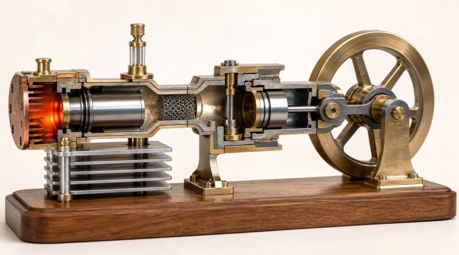
Updated August 7, 2026. A Stirling engine can look deceptively simple: heat one end, cool the other, turn the flywheel and watch it run. Inside, however, useful work depends on a timed pressure cycle. The working gas must move between hot and cold spaces with little leakage, low mechanical friction and limited flow resistance. A regenerator can improve that cycle by temporarily storing heat that would otherwise shuttle uselessly between the heater and cooler.
Quick answer
A Stirling engine regenerator is a porous heat-storage element in the internal gas path. During one part of the cycle, hot working gas passes through the matrix and transfers heat to it. During the reverse flow, cooler gas recovers part of that stored heat before returning to the hot space. An effective regenerator reduces the external heat that must be supplied and rejected for each cycle.
Crank phase angle controls when volume changes occur relative to gas transfer between the hot and cold spaces. A quarter-cycle relationship—often described as about 90 degrees—is a common starting geometry, not a universal tuning number. The correct interpretation depends on engine type, which crank event is used as the reference, linkage geometry, dead volume, leakage, friction and heat-exchanger behavior. If a model will not run, check free motion, temperature difference, seals and rubbing before changing the phase or packing the gas path with more matrix material.
Key findings
- The regenerator stores heat temporarily; it is not a fuel, heater, cooler or power piston.
- Regenerator effectiveness and flow resistance must be balanced. More material can increase heat-transfer area but also increase pressure drop and dead volume.
- Phase angle coordinates gas displacement with expansion and compression; its optimum is design- and objective-specific.
- Some small models have an obvious mesh regenerator, while others rely partly on the transfer passage, displacer clearance or adjacent metal surfaces.
- A non-running model is more often diagnosed efficiently by testing friction, thermal gradient, leakage and clearance in order than by immediately changing the crank timing.
- A display model can demonstrate the cycle, but it does not prove efficiency, output power or regenerator effectiveness without traceable testing.
The four spaces that make a Stirling engine work
A Stirling engine is a closed-cycle external-heat engine. The same working gas remains inside the engine while being heated, expanded, cooled and compressed. An idealized explanation divides the machine into four functional regions:
- Hot expansion space: gas receives heat and tends to expand at high temperature.
- Heater: the external heat source transfers energy through a wall into the working gas.
- Regenerator and transfer path: gas moves between hot and cold regions while exchanging heat with an internal matrix.
- Cool compression space and cooler: gas rejects heat and can be compressed with less work at a lower temperature.
Ohio University's Stirling Cycle Machine Analysis develops the ideal cycle into increasingly realistic models. NASA's Stirling Engine Design Manual likewise treats heater, cooler, regenerator, pressure losses, dead spaces and mechanical design as an interacting system. The practical implication is important: a perfect-looking linkage cannot compensate for a weak temperature difference, a serious leak or excessive flow loss.
What the regenerator actually stores
The regenerator stores thermal energy in its solid matrix. It does not store the working gas as a tank would. Imagine a fine metal mesh, stacked screens, woven wire or another porous structure placed where gas reverses direction every cycle. When hot gas flows toward the cold side, the matrix absorbs some of its heat. When the gas returns, the matrix gives part of that heat back.
Simon Fraser University's Stirling-cycle notes show why ideal regeneration matters: heat rejected internally during one constant-volume process is returned internally during the reverse process. In the idealized limit, that internal exchange reduces the external heat required for the same cycle. Real regenerators are not perfect, so some heat is lost and additional pumping work is required.
Why “add more mesh” is not a complete solution
A regenerator needs enough surface area and heat capacity to exchange heat rapidly, but the gas must still pass through it. Packing a transfer passage more densely may improve heat contact while simultaneously increasing pressure drop. Extra matrix also occupies volume, can create unwanted dead space, may shed fibers or particles and can make assembly tolerances more critical.
Peer-reviewed studies describe this as an optimization problem rather than a one-direction rule. The International Journal of Energy Research study on optimal regenerator performance analyzes the balance between thermal behavior and loss. An Applied Energy study reports very high effectiveness for a particular sub-regenerator and thermal-mass-ratio design, but its geometry and results should not be copied as a universal miniature-engine prescription.
For a purchased model, do not insert steel wool, screens or loose fibers unless the manufacturer specifies the material, quantity and location. A changed matrix can create rubbing, contamination, blockage or a fire hazard near a heater.
Where the regenerator is in a model
In a large or purpose-designed Stirling machine, the regenerator may be a distinct component between heater and cooler. In a compact demonstration engine, it may be less obvious. Part of the heat-storage function can be distributed across a narrow annulus around the displacer, a transfer tube or adjacent metal surfaces. That does not make every metal wall an efficient regenerator; it means visual inspection alone may not reveal the intended thermal design.
Before describing a specific model as “regenerative,” look for an exploded diagram, a documented matrix, a cutaway or a manufacturer statement. If none exists, record the regenerator construction as unknown. The Stirling Engine Kits collection contains several layouts, but a product photograph should be used to identify visible components, not to infer measured thermal performance.
Phase angle: what it controls
The crank phase relationship coordinates two actions: moving gas between temperature zones and changing the total working volume. In an alpha engine, separate hot and cold pistons both change volume. In beta and gamma engines, a displacer moves gas while a power piston performs most of the net volume change. The linkage must create higher pressure when the power piston can receive useful work and lower pressure when compression occurs.
A quarter-cycle separation is common because it creates an alternating sequence rather than making both motions peak together. But “90 degrees” can be ambiguous. One builder may measure crank-pin separation; another may describe the lead of the displacer relative to the power piston; a third may reference top dead center. Mirroring the linkage can also reverse the apparent direction. Always define the reference event before comparing angles.
Why the optimum is not always one number
An idealized engine may use a 90-degree phase relationship, yet a real optimum can shift because pressure does not change instantaneously. Gas needs time to flow through heater, regenerator and cooler. Heat transfer, leakage, mechanical drag and pressure drop introduce delays and losses. The angle that maximizes starting margin may differ from the angle that maximizes indicated work or thermal efficiency.
A published thermodynamic analysis of a modeled solar Stirling engine found maximum net work near 90 degrees and maximum efficiency near 110 degrees in that particular model. This is useful evidence that objectives can differ; it is not proof that every tabletop engine should be reset to 110 degrees. Model type, linkage and definitions must match before a number can be transferred.
Engine types and what to inspect
| Type | Moving elements | Regenerator clue | Timing clue |
|---|---|---|---|
| Alpha | Separate hot and cold power pistons | Often in the connecting heater–cooler path | Compare piston lead using a stated crank reference |
| Beta | Displacer and power piston share one cylinder axis | May be a dedicated matrix or integrated flow path | Check displacer lead and internal clearance |
| Gamma | Displacer cylinder plus a separate power cylinder | Transfer passage and displacer annulus deserve inspection | Crank-pin relationship is visible but convention still matters |
| Low-temperature-difference | Usually a large displacer and lightweight linkage | Very low flow loss and heat leakage are especially important | Small friction or clearance errors can prevent starting |
A seven-step diagnosis when a model will not run
Use the least invasive checks first. Do not disassemble a new engine until you have read its manual and confirmed that doing so will not affect safe operation or warranty.
1. Check free motion while the engine is cold
With no flame, hot plate or electrical heater active, turn the flywheel gently through a complete cycle. Look for a repeatable tight spot, scraping sound, bent link, side-loaded bearing or crank that touches the frame. A healthy small model should feel consistent; compression pulses may be noticeable, but metal-to-metal binding is not normal. Do not force a jammed mechanism.
2. Confirm a real temperature difference
A Stirling engine needs a hot side and a cooler side, not merely a warm engine. Use only the heat source stated by the manufacturer and allow the specified warm-up time. Keep cooling fins unobstructed. If both ends become nearly the same temperature, the pressure cycle weakens even though the whole engine feels hot. Never increase flame size or heater power beyond the product instructions.
3. Look for obvious leakage without pressurizing the model
Loose cylinder heads, damaged tubing, displaced gaskets and poorly seated power pistons can lose the pressure variation that drives the flywheel. Inspect fasteners and seals visually. Do not use compressed air, solvents or immersion tests unless the manufacturer explicitly provides that procedure. Some designs use intentionally loose low-friction fits, so “tightening everything” is not a universal remedy.
4. Verify the documented phase relationship
Compare the crank-pin positions with the assembly drawing at a clearly defined reference point, such as power-piston top dead center. Confirm which element leads in the intended direction of rotation. If the model was factory assembled and previously ran, phase is less likely to have changed than a loose set screw or slipped crank. Mark original positions before any authorized adjustment.
5. Inspect displacer clearance and rubbing
The displacer must move gas without acting like a tightly sealed power piston. A bent rod, off-center cap or thermal expansion can cause intermittent rubbing. Beta and gamma models are particularly sensitive because the displacer travels inside a close surrounding space. A cold engine that turns freely but binds only after heating may have a thermal-clearance problem.
6. Restore heat rejection on the cold side
Dust, blocked fins, a missing fan belt or poor contact with a cooling plate can raise cold-side temperature. Let the engine cool completely before cleaning. Use dry, non-abrasive methods unless the manual permits another process. The goal is to preserve the temperature difference, not to cool the hot cap directly or create thermal shock.
7. Suspect regenerator or internal heat-transfer loss last
If motion, heat source, cooling, seals, phase and clearance are correct, internal flow resistance or weak heat exchange becomes more plausible. This is the point to consult an exploded drawing or the manufacturer. Do not add improvised mesh. Regenerator diagnosis may require temperature, pressure or indicated-work measurements that a display model does not provide.
A practical model-selection framework
Choose a Stirling model by the question you want to study, not by cylinder count alone. A visible gamma linkage makes displacer/power-piston phase easy to observe. A beta engine gives a compact shared-axis arrangement. Multi-cylinder models show crank phasing across repeated working spaces. Heat-powered fans demonstrate external heat use but may hide internal components.
For a clear gamma layout, compare the ENJOMOR Gamma Stirling Helicopter Model Kit with the ENJOMOR Balance-Beam Stirling Generator Kit. A compact beta arrangement is represented by the ENJOMOR Mini Beta Hot-Air Stirling Engine. For repeated phase relationships, the 16-Cylinder Double-Tank Stirling Engine Model and 16-Cylinder Swash-Plate Stirling Engine Model provide different visible mechanisms.
For applied heat-transfer demonstrations, browse Heat-Powered Stirling Models & Devices. For complex phasing, use the Multi-Cylinder Stirling Engine Models subcategory. These links identify current public listings. They do not certify an output, efficiency, lifetime or internal regenerator construction unless that value is documented on the specific product page.
What a tabletop model can and cannot prove
A transparent or open-frame model can reveal crank order, displacer motion, flywheel inertia and the location of heater and cooler. It can make phase relationships visible and help a learner predict the direction of gas movement. If the engine operates, it demonstrates that a temperature difference can sustain its mechanical losses at that condition.
It cannot by observation alone establish thermal efficiency, indicated power, regenerator effectiveness, gas pressure, safe heater input or a universal phase optimum. Those quantities require documented instrumentation and test conditions. A generator lighting an LED proves that some electrical energy reached the LED; it does not establish a stable rated output without measurements.
Safety and evidence limits
- Use only the specified heat source, fuel, wick, voltage and operating procedure.
- Operate on a stable, non-combustible surface with ventilation and adult supervision where required.
- Keep hands, hair and loose objects away from the flywheel and linkage.
- Treat the hot cap, burner, exhaust products and nearby metal as burn hazards.
- Allow complete cooling before inspection, cleaning or adjustment.
- Do not pressurize, modify or repack an engine unless its manufacturer provides the procedure.
This article explains general engineering principles. Product-specific materials, clearances, phase settings, heater limits and maintenance instructions must come from the current manual. If those values are absent, record them as unknown rather than inferring them from a similar-looking model.
Frequently asked questions
Does every Stirling engine need a regenerator?
Ideal Stirling-cycle efficiency assumes perfect regeneration, but real small engines vary. Some have a distinct porous matrix; others distribute heat storage through passages and nearby surfaces. An engine can run with weak regeneration, but it generally needs more external heat and rejects more heat for the same idealized cycle.
Is 90 degrees the correct Stirling engine phase angle?
It is a common starting relationship, not a universal setting. The reference convention, engine type, linkage, flow delay and performance objective matter. Use the assembly drawing for the specific engine and define which component leads.
Why does my Stirling engine run only after a hard flick?
The flywheel may be overcoming initial friction or carrying the mechanism through a weak part of the cycle. Check cold free motion, warm-up, cooling, leakage, clearance and documented phase in that order. A harder flick is not a substitute for correcting binding or inadequate temperature difference.
Can steel wool be used as a regenerator?
Metal fibers can provide heat-transfer area in some designs, but grade, packing density, cleanliness, temperature resistance and pressure drop matter. Do not add steel wool to a product unless the manufacturer specifies it.
Does a better regenerator always increase power?
No. Better heat recovery can reduce required heat input, but extra flow resistance, dead volume or poor temperature distribution can reduce pressure variation and power. The complete engine must be optimized.
How can I see the phase relationship on a gamma engine?
Identify the power-piston crank and the displacer crank, turn the cold engine slowly, and note which reaches its reference position first in the intended rotation direction. Compare that observation with the product drawing rather than relying on an unlabeled online photograph.
What should I check first when a Stirling model stops running?
Let it cool, then check free movement and obvious mechanical interference. Next verify the specified heat source, cooling path and seals. Only after those checks should you investigate phase adjustment or internal regenerator changes.
Conclusion
The regenerator is best understood as a reversible internal heat store. It receives heat from gas moving toward the cold side and returns part of that heat when the flow reverses. Its design must balance heat capacity and heat-transfer area against pressure drop, dead volume and mechanical practicality.
Phase angle is the schedule that coordinates gas transfer with expansion and compression. A quarter-cycle relationship is a useful starting concept, but a real engine's best setting depends on its architecture, definition and losses. For troubleshooting, the most reliable path is also the least dramatic: confirm free motion, preserve the temperature difference, inspect leakage and clearance, verify the documented phase, and only then suspect the regenerator. That sequence turns a vague “it will not run” problem into testable engineering questions.
References
- NASA / U.S. Department of Energy, Stirling Engine Design Manual, 1978; accessed August 7, 2026.
- Ohio University, Stirling Cycle Machine Analysis; accessed August 7, 2026.
- Simon Fraser University, Stirling Cycle course notes; accessed August 7, 2026.
- Andresen et al., “Stirling engine regenerators: How to attain over 95% regenerator effectiveness with sub-regenerators and thermal mass ratios”, Applied Energy, 2019.
- Organ and Finkelstein, “Optimal regenerator performance in a Stirling engine”, International Journal of Energy Research.
- Al-Saffar, “Thermodynamics Performance Analysis of Solar Stirling Engines”, 2012.
- Hooshang et al., Stirling-engine thermodynamic performance study, Energies, 2018.
- Ohio University, Making Stirling Engines; accessed August 7, 2026.
- U.S. Department of Energy / OSTI, The Regenerator and the Stirling Engine; accessed August 7, 2026.
Leave a comment