

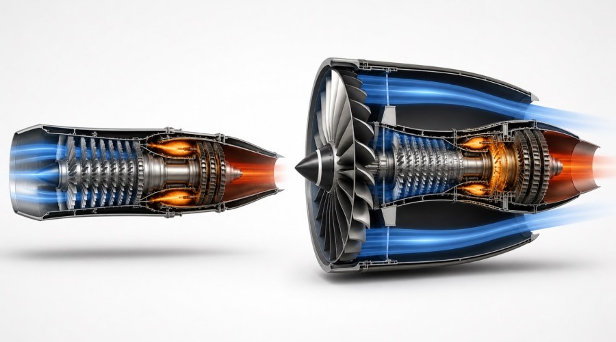
Updated August 6, 2026. A turbojet and a turbofan share the same gas-turbine core idea: compress air, add heat in a combustor, expand the gas through turbines, and produce thrust. The decisive difference is what happens to the incoming air and where most of the useful propulsive work is done. A turbojet sends essentially all inlet airflow through the core. A turbofan adds a fan and bypass duct so part, and sometimes most, of the airflow travels around the core.
Quick answer
In a turbojet, the compressor, combustor, turbine and exhaust nozzle form one main flow path. The engine produces thrust by accelerating a relatively smaller mass of air to a high exhaust velocity. In a turbofan, the gas-generator core also drives a fan. The fan accelerates an additional bypass stream that does not pass through the combustor. A high-bypass turbofan therefore produces much of its thrust by giving a relatively small velocity increase to a much larger mass of air.
Bypass ratio is a mass-flow ratio, not a simple diameter ratio. NASA defines it as bypass-stream mass flow divided by core-stream mass flow. A stated bypass ratio of 10:1 means approximately ten units of air mass travel through the bypass stream for every one unit through the core at the specified operating condition. Diameter is a useful visual clue, but it is not a measurement of bypass ratio.
Key findings
- Both engines contain a compressor, combustor and turbine; the fan and bypass flow are the architectural separator.
- A turbojet has a bypass ratio of zero in the ideal classification because all inlet flow goes through the core.
- A turbofan divides inlet flow into core and bypass streams; low- and high-bypass designs occupy different points on a continuum.
- For a required thrust at subsonic transport speed, moving more air with a smaller velocity increase can improve propulsive efficiency.
- Higher bypass is not an unconditional synonym for “better.” Diameter, drag, mass, installation, flight speed, thrust density and noise sources create mission-level trade-offs.
- A cutaway model can show flow architecture, shaft layout and blade stages, but it does not by itself prove an engine's operating bypass ratio, thrust or efficiency.
Turbofan vs turbojet at a glance
| Feature | Turbojet | Turbofan |
|---|---|---|
| Main airflow | Essentially all inlet air passes through the gas-generator core | Inlet air is divided between core flow and bypass flow |
| Front component | Compressor inlet; no separate thrust-producing bypass fan | Fan ahead of the core, usually visibly larger on high-bypass designs |
| Bypass ratio | Zero by ideal classification | Greater than zero; value depends on engine and operating point |
| Thrust production | Dominated by high-velocity core exhaust | Combination of fan/bypass thrust and core exhaust thrust |
| Typical visual form | Slender core and nozzle | Fan plus an annular bypass duct around the core |
| Common mission logic | High specific thrust and compact frontal area | Efficiency, thrust and installation balanced for the aircraft mission |
This table describes architecture, not a universal performance ranking. Two engines can have different pressure ratios, turbine temperatures, fan pressure ratios, nozzle arrangements and installation losses. A fair comparison requires a defined flight condition and mission.
The shared gas-turbine core
Start with what the two engines share. The inlet delivers air to a compressor. Compressor stages raise pressure. Fuel is added and burned in the combustor. Hot gas expands through one or more turbine stages, which extract enough shaft power to drive the compressor and, in a turbofan, the fan. The remaining flow expands through a nozzle and contributes thrust.
The FAA's Pilot's Handbook of Aeronautical Knowledge describes the turbofan as combining features of the turbojet and turboprop: a secondary airflow is diverted around the combustion chamber, while the core remains a self-sustaining gas turbine. This is why saying “the fan replaces the jet engine” is misleading. The core powers the fan through the turbine and shaft system; the fan changes how the engine distributes energy to the surrounding air.
What bypass ratio actually measures
NASA writes the relationship as:
Bypass ratio = bypass mass flow ÷ core mass flow
The definition contains three important limits:
- It is based on mass flow. A photograph can suggest high or low bypass, but only design or measured flow data establish the ratio.
- It is not the percentage of total thrust from the fan. Bypass ratio describes airflow division. Fan-thrust share also depends on the velocity and pressure changes in both streams.
- It can be operating-condition dependent. Published values normally refer to a defined design convention or condition. Off-design airflow does not have to preserve one exact ratio.
A low-bypass turbofan may look close to a turbojet because the fan diameter and core diameter are similar and the bypass duct is narrow. A high-bypass transport engine has a much larger fan and a visibly smaller core nested inside the nacelle. The classification is continuous, not a set of perfectly sharp visual boxes.
Why moving more air more slowly can be efficient
Thrust depends on the rate of change of momentum. In simplified language, an engine can create a required momentum change by accelerating a smaller mass flow by a large amount or a larger mass flow by a smaller amount. The energy left in the wake depends on velocity squared, so an unnecessarily high jet velocity can carry away energy that does not become useful aircraft propulsive work.
MIT's Unified Engineering propulsion notes show the trade-off between propulsive efficiency and specific thrust. Higher exhaust velocity can deliver more thrust per unit mass flow and a smaller inlet area, but propulsive efficiency tends to improve when the exhaust velocity is closer to the flight velocity. Transport aircraft therefore accept a larger fan and inlet to move more air with a smaller velocity increment. Aircraft needing compact frontal area, high specific thrust or different high-speed performance may favor a smaller bypass stream.
This reasoning does not mean the fan creates free thrust. The turbine must extract core-gas energy to turn the fan. Fan, turbine, duct and gearbox losses may be introduced. The benefit is a better match between delivered momentum change and the aircraft's speed and mission.
Where the thrust comes from
NASA's turbofan thrust equation treats the core and fan as two contributing streams. The fan stream has its own mass flow and exit velocity; the core stream has another. Total thrust also includes pressure terms in a complete analysis. The practical lesson is that there is no safe universal statement such as “every turbofan gets 90 percent of its thrust from the fan.” That fraction varies with bypass ratio, fan pressure ratio, nozzle design and flight condition.
For a turbojet, the useful visual story is simpler: there is no separate bypass fan stream. Compressor airflow proceeds through the combustor and turbine to the nozzle. For a high-bypass turbofan, the large front fan and annular duct make the two-stream architecture obvious. A low-bypass engine sits between those extremes.
Efficiency: propulsive, thermal and overall
“More efficient” is incomplete unless the efficiency is named.
- Thermal efficiency concerns how effectively fuel energy becomes mechanical and jet energy. Pressure ratio, component efficiency and turbine temperature matter.
- Propulsive efficiency concerns how effectively that energy becomes useful aircraft power rather than excess wake kinetic energy.
- Overall efficiency combines the two.
- Thrust-specific fuel consumption compares fuel mass flow with produced thrust at a stated condition.
NASA's specific-fuel-consumption guide uses a simplified turbojet/turbofan comparison to illustrate why lower TSFC means more thrust for a given fuel flow, or less fuel for a given thrust. It also warns that TSFC changes with speed and altitude. Do not use one sea-level number to predict every mission segment or compare unrelated engines without their test conditions.
Noise: a real benefit with an important qualification
Early turbojets and low-bypass engines were strongly affected by high-velocity jet mixing noise. ICAO reports that the move toward higher-bypass engines reduced jet velocity and contributed to large historical noise improvements. However, “higher bypass equals silent” is false. On modern large aircraft, fan noise can dominate important operating conditions, while airframe, turbine, combustor and installation noise also matter.
ICAO's current noise-technology guidance says fan noise is a major source for modern large aircraft and that acoustic liners in the inlet and bypass duct are important. This changes the engineering problem rather than eliminating it. A model cutaway can reveal where these sources originate, but it cannot demonstrate certified sound levels.
Low-bypass and high-bypass turbofans
Low-bypass turbofan: a smaller fraction of inlet flow bypasses the core. The engine can retain relatively high specific thrust and compact diameter. Many military applications use low-bypass turbofans, sometimes with afterburners, but aircraft and mission details matter.
High-bypass turbofan: the fan moves a much larger bypass flow around the core. This architecture is strongly associated with subsonic transport because of its propulsive-efficiency and noise advantages, but it also increases fan diameter and creates installation, weight, drag, ground-clearance and structural constraints.
NATO educational material on mission-defined engine cycles makes the central point: engine selection is an optimization problem. Flight Mach number, thrust requirement, inlet area, augmented operation, fuel consumption and aircraft packaging must be evaluated together. A bypass ratio cannot be judged apart from the mission.
How to identify each architecture in a cutaway
- Find the combustor. It marks the hot core. Trace the compressor stages ahead of it and turbine stages behind it.
- Look for a separate front fan. On a turbofan, the fan is mechanically connected to a turbine spool but is not simply another core compressor stage.
- Trace the bypass duct. A continuous annular passage around the core is the strongest visual evidence of a turbofan.
- Compare fan and core diameters. A very large fan around a compact core suggests high bypass; a narrower passage suggests low bypass. This remains a qualitative clue.
- Trace shafts and spools. Multi-spool layouts allow compressor, fan and turbine groups to rotate at different suitable speeds.
- Inspect the exhaust arrangement. Some turbofans keep core and bypass exhaust separate; others mix them before a common nozzle.
The Smithsonian's National Air and Space Museum provides useful real-object references. Its General Electric J85 cutaway is cataloged as a single-shaft turbojet with an eight-stage axial compressor and two-stage turbine. Its Rolls-Royce RB211-22 cutaway is cataloged as a three-shaft turbofan with a separate fan, intermediate- and high-pressure compressors, and corresponding turbine groups. Those records show how museum metadata can confirm what a cutaway suggests.
A six-question model-selection framework
For a learning model, choose the architecture that answers the question you want to study. Start with the Turbofan & Jet Engine Kits collection and compare current product documentation with these six questions:
- Can you clearly see the core compressor, combustor and turbine?
- Can you trace a separate bypass passage from inlet to outlet?
- Does the model show one spool or multiple concentric spools?
- Are fan, compressor and turbine stages mechanically linked in a physically understandable way?
- Is the model a static cutaway, hand-cranked assembly, electric demonstration, combustion demonstration or actual thrust-producing device?
- Does the seller provide model-specific scale, dimensions, materials, assembly level and operating limitations?
For a compact turbojet layout, the SKYMECH WP-85 turbojet model kit offers a different flow path from the A38X cutaway turbofan model. For a visible fan/core relationship, compare the TECHING DM122 mini turbofan kit and the SKYMECH TR900 STEM kit.
Advanced builders may prefer a multi-spool representation such as the TECHING dual-spool turbofan kit, while the TECHING 1:10 full-metal turbofan kit emphasizes a more extensive assembly. The SKYMECH WS-15 model is useful for discussing a compact fighter-style arrangement. These links identify the listed products; they do not certify real-engine performance or imply that a model reproduces every dimension of its inspiration.
What a model can and cannot prove
A well-made model can explain component order, relative diameter, shaft grouping, airflow separation and mechanical motion. It can support questions such as “where does bypass air travel?” and “which turbine drives the fan?” It cannot establish certified thrust, fuel consumption, noise, safe operating speed or an exact bypass ratio unless those values are supplied and traceable for the specific product.
Be especially careful with electrically driven or hand-cranked displays. Rotating blades can demonstrate mechanical relationships without reproducing gas temperature, pressure ratio, spool speed or aerodynamic loading. A combustion demonstration adds fuel, ignition and hot-section hazards; it still should not be treated as a certificated flight engine.
Safety and evidence limits
Do not operate a fuel-burning demonstration engine from a general educational article. Follow the exact manufacturer manual, use the specified fuel and starting system, secure the unit to a suitable test stand, provide ventilation and fire controls, protect hearing and eyes, and keep people out of the intake and exhaust planes. Never place a hand, tool or loose object near an inlet, exposed rotor or hot nozzle.
This article explains general architecture. Published performance values for real engines apply only to their documented configuration and condition. Product-page statements, scale labels and supplier specifications should be checked against the current manual. If a model's bypass ratio, spool speed, fuel, temperature limit or operating purpose is not documented, record it as unknown.
Frequently asked questions
Is a turbofan a type of jet engine?
Yes. It is an air-breathing gas-turbine propulsion system. “Jet engine” is the broad family term; turbojet and turbofan describe different architectures within that family.
Is a turbofan just a turbojet with a fan?
That description is a useful first approximation, but incomplete. The added fan requires turbine work, shaft architecture, bypass ducting, inlet and nozzle design, and a different distribution of energy between core and bypass streams.
Does bypass air go through the combustor?
No. By definition, bypass air travels around the core combustor. Core air passes through the compressor, combustor and turbines.
Does a higher bypass ratio always mean lower fuel consumption?
No universal rule is valid without a mission and operating condition. Higher bypass can improve propulsive efficiency at suitable subsonic conditions, but engine mass, diameter, drag, pressure ratio, fan efficiency and aircraft installation also affect fuel burn.
Why do fighters often use low-bypass turbofans?
Many fighter missions value compact frontal area, high specific thrust, high-speed performance and afterburning capability. That trade differs from a subsonic transport mission. Not every fighter or operating point is identical.
Can I estimate bypass ratio from fan diameter?
You can make a qualitative classification, but not a reliable numerical estimate. Bypass ratio is based on mass flow, which depends on annular areas, velocities, density and engine operating condition.
Which is quieter: turbojet or turbofan?
Modern higher-bypass designs have greatly reduced the high-velocity jet-noise problem associated with early turbojets, but turbofans still produce fan, turbine, combustor and installation noise. Certified noise data are required for an actual aircraft comparison.
Which cutaway should a beginner choose?
Choose the model that makes the intended flow path easiest to trace. A turbojet cutaway is simpler for learning the core cycle. A turbofan cutaway is better for studying bypass flow, fan drive and multi-spool relationships. Clear documentation matters more than part count alone.
Conclusion
The cleanest difference between turbojet and turbofan engines is the airflow map. A turbojet routes inlet air through one gas-generator path and relies on high-velocity core exhaust. A turbofan uses the core to drive a fan and divides the inlet flow into core and bypass streams. Bypass ratio measures that mass-flow split.
Once the airflow is clear, the trade-off becomes understandable. High specific thrust favors a large velocity change through a smaller mass flow; high propulsive efficiency at subsonic transport conditions favors a smaller velocity change through a larger mass flow. Real engines balance those goals with thermal efficiency, noise, mass, diameter, drag and mission requirements. A good cutaway does not replace performance data, but it makes the architecture visible enough to ask the right questions.
References
- NASA Glenn Research Center, Turbofan Thrust, updated May 13, 2021; accessed August 6, 2026.
- NASA Glenn Research Center, Specific Fuel Consumption, updated May 13, 2021; accessed August 6, 2026.
- Federal Aviation Administration, Pilot's Handbook of Aeronautical Knowledge, Chapter 7, accessed August 6, 2026.
- MIT OpenCourseWare, Unified Engineering: Propulsive Efficiency and Specific Thrust, accessed August 6, 2026.
- International Civil Aviation Organization, Reduction of Noise at Source, accessed August 6, 2026.
- International Civil Aviation Organization, Noise Reduction Technology, accessed August 6, 2026.
- National Air and Space Museum, General Electric J85-GE-17A Turbojet Engine, Cutaway, accessed August 6, 2026.
- National Air and Space Museum, Rolls-Royce RB211-22 Turbofan Engine, Cutaway, accessed August 6, 2026.
- NATO Science and Technology Organization, The Mission Defines the Cycle: Turbojet, Turbofan and Variable Cycle Engines, accessed August 6, 2026.
Leave a comment