

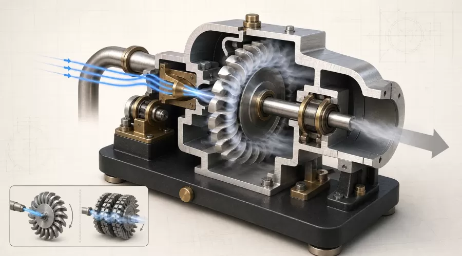
Quick answer: A model steam turbine turns a shaft by accelerating a working fluid through a nozzle or fixed blade row, then changing that flow's momentum across moving blades. In a simple impulse model, most of the pressure drop occurs before the rotor and the high-speed jet pushes on bucket-shaped blades. In a reaction stage, pressure also falls through the moving blades, so both momentum change and reaction contribute to torque. A visible spinning rotor proves motion; it does not by itself prove high efficiency, safe pressure capability, or useful output power.
This guide explains what you can reasonably infer from a tabletop turbine, what you cannot infer without measurements, and how to plan a conservative test. It is written for buyers, educators, and builders comparing a model steam engine, a single-stage desktop steam turbine, or a multi-stage turbine model.
Key takeaways
- The nozzle is an energy-conversion component, not merely a pipe: it trades pressure and enthalpy for flow velocity.
- Impulse and reaction describe where expansion occurs; they do not automatically identify which model is “better.”
- A small rotor can reach high speed while producing little usable torque, so speed and power must not be treated as synonyms.
- Nozzle alignment, rotor clearance, bearing friction, exhaust restriction, condensate, and load all affect whether a model starts and runs steadily.
- Use only the manufacturer's specified working fluid, fittings, limits, guarding, and operating procedure. Never improvise a sealed boiler or increase pressure to cure poor performance.
The energy path: pressure to velocity to shaft work
A turbine does not rotate simply because “steam pushes the blades.” The useful explanation has three steps. First, the working fluid contains thermodynamic energy associated with its state and pressure. Second, a nozzle or stationary blade passage accelerates and directs the flow. Third, the rotor turns because the moving blades change the speed and direction of that flow, producing a force and torque on the shaft.
Penn State's engineering lesson on steam turbine stages and degree of reaction explains how stationary passages act as nozzles and how the pressure change is distributed. MIT OpenCourseWare separately treats impulse turbines, velocity compounding and blade stress, reinforcing an important lesson: the rotor, nozzle and operating speed form one system.
Why flow direction matters
Torque depends on the change in the fluid's tangential momentum, not only on how much fluid passes through the casing. A nozzle aimed at the wrong radius or angle can create a dramatic plume yet transfer little useful torque. The inlet jet should meet the intended blade region and leave with less tangential momentum than it entered with. Exact angles are design-specific, so a buyer should not assume that a generic hose or replacement nozzle is compatible.
Why speed is not power
Rotational speed is how fast the shaft turns. Torque is the turning moment available at that shaft. Mechanical power is their product. A lightly loaded miniature rotor may accelerate to an impressive speed because its required torque is small. Add a generator, propeller, belt or brake, and speed may fall sharply. Therefore, a no-load demonstration cannot establish generator output, model-boat suitability, efficiency, or continuous-duty capability.
Impulse versus reaction: the practical distinction
Both arrangements use momentum change, but the location of the pressure drop differs. The process-machinery reference hosted by Carnegie Mellon University distinguishes impulse and reaction turbine stages: an impulse stage takes its principal energy drop in the stationary nozzle, while a reaction stage divides expansion between stationary and moving passages.
| Feature | Simple impulse model | Reaction or impulse-reaction model |
|---|---|---|
| Main pressure drop | Primarily in the stationary nozzle | Across stationary and moving blade passages |
| Rotor role | Deflect a high-speed jet and extract momentum | Deflect flow while part of the expansion continues |
| Typical visual clue | One or more discrete nozzles aimed at a bucketed wheel | Alternating fixed and moving rows or carefully shaped passages |
| Model advantage | Mechanism is easier to see and explain | Shows staging and distributed expansion more clearly |
| What appearance cannot prove | Efficiency, pressure rating, balance quality, safe speed, output power or working-fluid compatibility | |
Industrial product families show that “impulse” can describe both single-stage and multi-stage machines. Siemens Energy's Dresser-Rand steam turbine portfolio, for example, lists impulse blading across several arrangements. That is useful evidence against a common shortcut: blade-row count alone does not determine whether a turbine is impulse or reaction.
What compounding changes
A single large energy drop can create a jet speed that is difficult to use efficiently in one wheel. Compounding divides the task across velocity stages, pressure stages, or both. A model with several wheels may therefore demonstrate staged extraction, but only if its stationary and moving rows are arranged to guide the flow correctly. Several decorative discs on one shaft are not sufficient evidence of genuine multi-stage behavior.
Seven components that determine whether a model runs well
1. Inlet and control valve
The inlet path must be suitable for the specified fluid, temperature and pressure. A valve controls flow; it is not permission to trap pressure upstream. The U.S. Department of Energy's Steam System Sourcebook treats turbines, pressure reduction, steam quality, traps, leaks and condensate recovery as interacting parts of a complete steam system. The same systems thinking is valuable at model scale even though industrial numbers must not be copied to a tabletop device.
2. Nozzle
The nozzle establishes jet direction and velocity. Its throat, exit shape, finish and alignment matter. If the opening is partly blocked, if a fitting protrudes into the passage, or if the jet misses the blade radius, starting torque falls. Do not drill a nozzle larger as a first response: that changes mass flow and may exceed the rest of the system's intended operating envelope.
3. Rotor and blades
The rotor must be balanced, securely retained and free from visible damage. Blade geometry determines how the flow is turned. A bent blade may increase vibration and reduce clearance. Never straighten, grind or rebalance a high-speed rotor unless the manufacturer supplies a procedure and the operator has the required competence.
4. Shaft, bearings and alignment
Bearing friction can consume much of the available torque in a small demonstration. With the model isolated, depressurized and cool, the shaft should behave as the manufacturer describes. Binding at one angular position suggests misalignment, contamination, a rubbing seal or rotor contact. Lubricant type and quantity are model-specific; more oil is not automatically better because viscous drag and contamination can also increase.
5. Casing and clearances
The casing contains and guides the flow and provides a physical boundary around the rotor. Clearances must allow rotation without excessive leakage. A cutaway display explains geometry, but an operating turbine should retain every guard and cover specified by its maker. OSHA's machine-guarding guidance identifies rotating parts and flying debris as hazards that safeguards are intended to control.
6. Exhaust
The exhaust must remain open and routed as designed. A restricted outlet raises back pressure and reduces the energy available across the turbine. With steam, a poorly arranged line can also collect condensate. HSE's water-hammer safety notice concerns industrial systems, but its core lesson transfers: condensate accumulation, drainage, valves and operating practice require deliberate control.
7. Load or generator
A coupled load changes the operating point. Before connecting anything, verify shaft interface, direction, maximum permitted speed, alignment and load limits from the actual product documentation. A small lamp glowing is qualitative evidence of electrical generation, not a calibrated power measurement. Voltage, current, speed and temperature should be measured with instruments suited to the expected range.
A conservative diagnostic sequence
This sequence is a decision framework, not a substitute for the model's manual. If the supplier's procedure differs, follow the product-specific instructions.
- Identify the exact model. Match the name, revision, fittings, rotor and accessories. Do not infer limits from a visually similar turbine.
- Read the rated conditions. Confirm permitted working fluid, inlet limit, temperature limit, lubrication, duty cycle, guarding and age restrictions. If any critical value is absent, mark it UNKNOWN and ask the seller or manufacturer.
- Inspect cold and isolated. Look for loose fasteners, damaged blades, foreign material, cracked tubing, misalignment and rotor contact. Do not spin with fingers near exposed blades.
- Verify the outlet. Confirm that exhaust routing is open, supported and unable to discharge hot fluid toward people or vulnerable surfaces.
- Start at the lowest specified input. Increase only within the written procedure. Never compensate for binding or poor nozzle alignment by exceeding the rating.
- Observe from a protected position. Watch for vibration, rubbing, leakage, unstable speed and abnormal sound. Stop immediately if the behavior changes unexpectedly.
- Test unloaded before adding a load. Establish a repeatable baseline, then add only a compatible load in small steps while monitoring speed and temperature.
- Shut down and cool. Isolate the energy source, release stored pressure by the approved method, allow hot parts to cool, and drain or dry only as directed.
Compressed air versus live steam
Compressed air can make the flow path and rotor motion easier to observe because it avoids hot condensate, but it is still stored-pressure equipment. Air testing does not prove that seals, lubricants, hoses or materials are suitable for steam temperature. Conversely, a product marketed for steam should not be connected to an improvised boiler. HSE advises using the lowest pressure that will do the job and operating within known safe limits in its introduction to pressure equipment.
| Question | Compressed-air demonstration | Live-steam operation |
|---|---|---|
| What it can show | Rotation, direction, basic nozzle/rotor response | Operation with the intended hot vapor when explicitly rated |
| Primary added hazards | Stored pressure, hose movement, flying parts, overspeed | All air hazards plus burns, hot condensate and boiler-related risks |
| What it cannot prove | Steam compatibility or thermal performance | Efficiency or useful power without measurements |
| Decision rule | Use only a documented, compatible source and stay inside the product-specific limits | |
For shoppers who want piston motion, valve gear and slow visible cycles rather than a high-speed rotor, the live steam engine and boiler category may answer a different learning goal. The existing model steam engine troubleshooting guide covers reciprocating-engine symptoms; it should not be used as a turbine service manual.
How to choose a model steam turbine
Use a five-part fit test instead of choosing by rotor count or claimed speed:
- Learning objective: impulse nozzle, reaction staging, generator coupling, machining, or historical display?
- Operating evidence: are the working fluid, limits, manual, replacement parts and required source explicitly documented?
- Visibility: can you see the flow path and rotor relationship without removing an operating guard?
- Measurement plan: do you need only qualitative motion, or will you measure speed, voltage, current, temperature or load?
- Safety fit: is there suitable supervision, guarding, ventilation, heat protection, exhaust routing and pressure equipment?
A steam-engine science kit can be the better choice when a classroom needs low-complexity observation. A multi-stage display can be more useful when the purpose is to trace stationary and rotating rows. Neither choice should be described as universally safest or best without product-specific evidence and a defined use case.
Limits of what a product page can establish
Photographs can support observations about visible layout, included parts and apparent scale. Supplier specifications may support model-specific dimensions or intended working fluid when they are clearly stated. They do not independently certify efficiency, material grade, safe pressure, durability, educational outcomes or suitability for a particular boiler. Those claims require direct documentation, test methods or recognized conformity evidence.
For that reason, this guide deliberately avoids universal speed, pressure and power numbers. Values differ by rotor, nozzle, fluid, temperature, bearings, load and instrumentation. When a required number is missing, the correct value is UNKNOWN, not zero and not a guess.
Frequently asked questions
Does a model steam turbine need a boiler?
Only if the exact model is designed for live steam and the compatible steam source is documented. Some models may be demonstrated with compressed air, but that does not prove steam compatibility. Never improvise a sealed vessel or connect an unknown pressure source.
Why does the turbine spin but fail to drive a load?
No-load speed requires relatively little torque. Bearing drag, nozzle misalignment, exhaust restriction, leakage or an excessive load can make the shaft slow sharply. Diagnose the system within the manual's limits rather than increasing pressure.
Is a multi-stage turbine always more efficient?
No. Staging can distribute expansion and velocity, but actual efficiency depends on blade and nozzle geometry, leakage, clearances, surface finish, operating conditions and load. A model's stage count alone cannot establish performance.
What is the easiest visual difference between impulse and reaction?
A simple impulse demonstrator often has a discrete nozzle aimed at a bucketed wheel. A reaction-style model usually shows alternating passages where expansion continues through moving rows. This is a clue, not a complete classification; documentation or a sectional flow-path diagram is better evidence.
Can I run the rotor with the cover removed?
Do not remove an operating guard unless the manufacturer explicitly designed and documented that mode. Covers may contain rotating parts or debris and keep people away from danger zones.
How should the model be stored after steam use?
Follow the maker's shutdown, cooling, drainage, drying and lubrication instructions. Do not open a hot or pressurized system. If the instructions are absent, obtain them before operation rather than inventing a procedure.
Conclusion
A model steam turbine is most useful when it makes the complete energy path visible: controlled inlet, acceleration through a nozzle or stationary row, momentum change across the rotor, shaft work and a clear exhaust. The impulse-versus-reaction label explains where expansion occurs, but it cannot substitute for product-specific limits or measurements. Choose the model around the learning objective, document every unknown, and treat high-speed rotation, hot vapor and stored pressure as engineering hazards rather than visual effects.
Leave a comment