

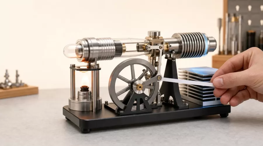
Updated July 29, 2026. Use this evidence-based H-F-L-P sequence—Heat, Friction, Leakage and Phase—to diagnose a Stirling engine model that will not run without immediately increasing the heat source.
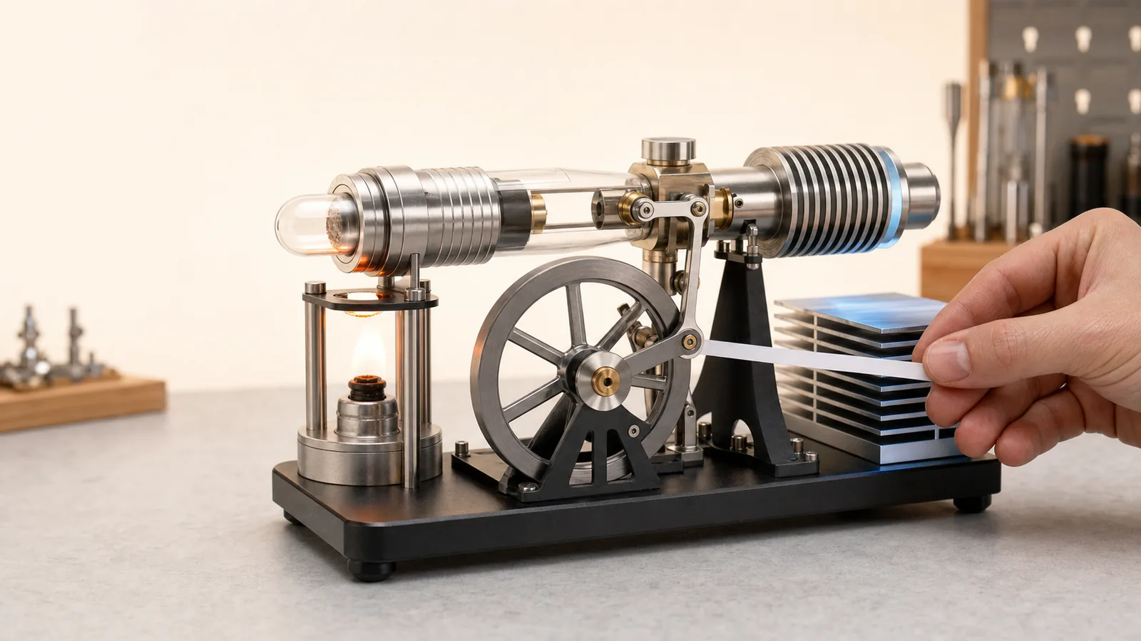
Original EnginesDIY editorial illustration. It shows a generic gamma-type Stirling model in a diagnostic workbench context; it is not a service diagram for a specific product.
Quick answer
When a small Stirling engine will not run, do not begin by adding more heat. First identify the engine type and its approved heat source. Then test whether the mechanism turns freely while cold, confirm that the hot and cold sides can develop a real temperature difference, look for evidence of excessive leakage, and verify the linkage phase and intended rotation direction against the supplied manual.
Most no-run symptoms fit four diagnostic paths:
- Heat path: the model is not receiving the kind of temperature difference its design needs.
- Friction path: bearings, rods, the displacer or a belt consume more work than the cycle can supply.
- Leakage path: pressure changes are lost through a joint, diaphragm or damaged seal.
- Phase path: the displacer and power piston are not moving in the relationship intended by the design.
This is an evidence-based diagnostic framework, not a replacement for the product manual. Heat source, maximum temperature, fuel, lubricant, rotation direction, clearances and disassembly procedures are model-specific. Stop if glass is cracked, a fuel component leaks, a hot part is loose, a piston binds, or the manual is missing.
Why a tiny Stirling engine can be difficult to start
A Stirling engine does not burn fuel inside its cylinder. Its working gas is heated and cooled repeatedly, producing pressure changes that act on a power piston. NASA’s explanation of dynamic Stirling power describes this as a closed thermodynamic process: gas is heated so its pressure rises, then cooled so pressure falls, while pistons convert the changing pressure into motion (NASA Science).
MIT’s teaching material separates the two important moving elements. The displacer transfers the working gas between hotter and cooler regions; the power piston changes the enclosed volume and delivers mechanical work to the crank and flywheel (MIT OpenCourseWare).
The useful output of a tabletop model can be very small. Colorado State University notes that its unpressurized low-temperature-difference demonstration produces less than one watt and may need time plus a slight starting turn (Colorado State University Physics). That figure describes CSU’s device, not every retail engine, but it explains the diagnostic principle: a small amount of drag or heat loss can consume the available work.
This is why “use a bigger flame” is a poor first test. More heat does not repair a tight bearing, rubbing displacer, slipping crank, open joint or wrong phase relationship. It can instead damage a model that was designed for a different heat source.
First identify which Stirling model you have
Troubleshooting starts with design classification because different models use different heat sources and starting behavior.
| Model family | Typical energy arrangement | What to verify first | Do not assume |
|---|---|---|---|
| Low-temperature-difference (LTD) | Warm plate/cup/hand on one side and cooler surroundings on the other | Correct plate orientation and a stable temperature difference | That an open flame is allowed |
| Flame-heated hot-air model | External burner heats a hot cap or cylinder | Correct fuel, burner placement and warm-up procedure in the manual | That more flame is safer or better |
| Generator model | Stirling mechanism drives a small generator or LED | Engine runs freely before the generator load is connected | That a dark LED proves the heat cycle failed |
| Multi-cylinder display model | Several cylinders and linkages share a crank | Every rod and crank turns freely and is installed in the correct order | That all cylinders use identical phase geometry |
| Vacuum-style or atmospheric model | Pressure difference and atmospheric action drive motion | The exact operating principle and direction in the supplied documentation | That it should be tested like a sealed Stirling engine |
If you are still choosing a format, compare the Stirling engine collection, heat-powered Stirling models and multi-cylinder Stirling models. The earlier guide to working, motorized, cutaway and live model engines explains why visible motion does not always mean the same energy conversion process.
The H-F-L-P diagnostic sequence
Use the order Heat, Friction, Leakage, Phase. The order matters because it avoids changing several variables at once.
H — Verify the heat path
A Stirling engine needs both a hot region and a cooler region. Heating the whole model uniformly does not create the alternating pressure-volume process that drives the crank. The U.S. Department of Energy’s OSTI record identifies heat-transfer rate and fluid-friction losses as performance constraints, and notes that coolant temperature affects output (OSTI).
Check the following without modifying the model:
- Read the supplied operating method. Determine whether the model is LTD, flame-heated, electrically heated or intended for another external source.
- Confirm orientation. On an LTD model, the designated plate must contact the warm or cool reservoir as instructed.
- Allow the specified stabilization time. Thick plates and cylinders need time for a gradient to develop.
- Keep the cold side able to reject heat. Do not wrap, cover or heat the cooling fins.
- Check whether the environment is defeating the gradient. A hot room, direct sunlight or a warm bench can reduce the cold-side difference.
- Use only the approved heat source. Purdue’s classroom LTD apparatus can operate with a small plate-to-plate difference and a gentle flywheel spin, but its stated temperature applies only to that particular apparatus (Purdue Physics).
For a heat-powered cup model, wait until the plate temperatures separate before judging it. For a flame-heated model, do not substitute a hotter fuel or enlarge the flame unless the product manual explicitly permits it.
F — Test friction while the engine is cold
Disconnecting or dismantling parts is not the first step. Begin with observation:
- With the engine cold and the approved heat source removed, turn the flywheel gently by hand.
- Feel for a repeatable tight spot at the same crank angle.
- Watch each rod, crank pin and bearing as the tight spot passes.
- Listen for rubbing, scraping or clicking.
- Confirm that the base is level and that the flywheel does not touch a frame or guard.
- If the model drives a belt, generator or accessory, follow the manual before changing belt tension or disconnecting the load.
MIT’s Stirling-engine model notes that component fit determines both friction and leakage and that system behavior changes as those losses change (MIT OpenCourseWare).
The diagnostic distinction is useful:
- Tight at one crank angle: look for alignment, rod contact, a bent shaft, a shifted flywheel or a displacer touching internally.
- Uniformly heavy rotation: look for overtight bearings, belt load, contaminated surfaces or the wrong lubricant.
- Free without the generator but heavy with it: the electrical or belt load may be dominating the tiny mechanical output.
- Free while cold but tight when warm: stop and let it cool; thermal expansion may be reducing clearance.
Do not add random oil to every moving part. The University of Iowa’s demonstration instructions use oil on particular bearings and graphite on a particular piston, while warning against over-lubrication and oil on another piston surface (University of Iowa Physics). That is a strong reason to follow the component-specific manual rather than a universal lubricant recipe.
How to separate friction from a heat problem
Use a simple two-condition test:
| Observation | Cold test | Heated test | More likely path |
|---|---|---|---|
| Flywheel stops at the same angle | Tight spot present | Same or worse | Friction/alignment |
| Flywheel coasts freely but never develops torque | Free | No sustained motion | Heat difference, leakage or phase |
| Mechanism improves after the model cools | Free again | Tight when hot | Thermal-expansion clearance |
| Piston pulses but flywheel will not continue | Mostly free | Small reciprocation only | Excess drag, weak gradient, generator load or phase |
| Engine starts, slows as temperatures equalize | Free | Runs briefly, then fades | Heat-rejection/temperature-difference limitation |
Record the observation before adjusting anything. A short video of one full crank revolution can reveal whether the same component binds repeatedly.
L — Check for leakage without assuming “perfectly airtight”
The working space must produce useful pressure changes, but “airtight” is not a universal pass/fail rule. Some power pistons use a deliberate close-running clearance; some models use diaphragms; some designs have equalization behavior specified by the manufacturer.
Safe, non-destructive checks include:
- inspect cylinder joints, caps and visible seals for displacement or damage;
- look for a loose fastener that the manual identifies as part of a sealed joint;
- inspect a diaphragm for tears, folds or an incorrect clamp position;
- turn the flywheel slowly and feel whether the power piston shows a repeatable compression response;
- compare the response with the manual or a known-good video for the exact model.
Do not use a household compressor, pressurize a glass cylinder or apply solvent to search for leaks. Do not tighten glass or acrylic assemblies beyond the supplied torque or hand-tightening instruction.
Research models include leakage among the non-ideal losses that change predicted pressure and power. A University of Sheffield study incorporates gas leakage and heat-transfer losses into a non-ideal beta-Stirling model (White Rose Research Online). This supports leakage as a real mechanism; it does not provide a universal retail-model leak limit.
P — Verify phase, linkage and rotation direction
The displacer must move the working gas between thermal regions at the appropriate part of the power-piston cycle. That relationship is created by crank geometry and linkage assembly.
Check:
- whether the crank disks, rods and spacers match the assembly diagram;
- whether a rod has been installed on the wrong side of a crank;
- whether a crank screw has slipped on its shaft;
- whether the displacer completes its stroke without touching an end;
- whether the manual specifies a starting direction;
- whether the flywheel is being nudged in that direction after the required warm-up.
Many simple Stirling explanations illustrate an approximate quarter-cycle relationship between displacer and power-piston motion, but do not use “90 degrees” as a universal repair setting. Multi-cylinder, rocking-beam, alpha, beta, gamma and vacuum-style models can use different visible geometry. The supplied assembly diagram is the controlling reference.
Symptom-based diagnosis
The flywheel will not turn by hand
Do not heat the engine. Remove the heat source, let every part cool, and inspect for shipping locks, frame contact, a bent rod, a displaced flywheel, a tight bearing or foreign material. If the model arrived assembled and the manual does not authorize adjustment, document the tight spot and contact support.
The flywheel turns freely but the engine never starts
Confirm engine type, heat-source compatibility, orientation, stabilization time and cold-side cooling. Then inspect visible seals and linkage phase. Do not keep increasing heat after the model reaches its stated operating condition.
The piston moves, but the flywheel only rocks
This indicates that some pressure variation exists, but it does not prove that the cycle produces enough net work. Check for a tight crank angle, generator/belt load, low temperature difference, displacer contact and a slipped crank.
The engine runs only after a strong push
A gentle starting nudge is normal for some demonstrations, but a forceful push can mask high friction. Compare the cold coast behavior with the manual. If the engine needs progressively more force, stop and inspect rather than increasing heat.
The engine starts and then slows
The temperature difference may be collapsing as the cold side warms or the hot reservoir cools. An LTD engine on a cup may naturally slow as the water approaches room temperature. A flame-heated model can also slow if cooling fins are obstructed or the generator load is excessive.
The LED does not light
First determine whether the engine itself reaches the required stable speed. A dark LED can result from low shaft speed, belt slip, generator connection or LED polarity; it does not by itself identify a thermal-cycle failure. The hot-air Stirling generator with color LED should be evaluated using the product’s own operating instructions.
A safe ten-minute diagnostic worksheet
- Record the exact product/model.
- Identify LTD, flame-heated, generator, multi-cylinder or other design.
- Confirm the approved heat source and starting direction.
- Remove heat and allow the model to cool fully.
- Rotate the flywheel gently through several revolutions.
- Mark any repeatable tight angle without forcing the mechanism.
- Inspect rods, crank pins, bearings, belts and visible seals.
- Restore only the manual-approved setup.
- Apply the approved heat/cooling arrangement for the stated time.
- Record whether the response is no movement, piston pulse, rocking, brief run or sustained run.
Change only one variable between tests. This makes the result interpretable and reduces the chance of hiding one fault with another adjustment.
When to stop
Stop operating immediately if:
- glass, acrylic or ceramic parts are cracked or chipped;
- fuel, vapor or liquid leaks from a burner;
- a flame contacts a part not intended for heating;
- the base becomes unstable;
- the mechanism binds more as it heats;
- a flywheel, crank or fastener is loose;
- water enters an LTD pressure chamber;
- wiring insulation softens or a generator smells hot;
- the model’s manual, fuel specification or heat-source limit is unavailable.
Allow the model to cool before touching, moving or adjusting it. Use the manufacturer’s ventilation, eye-protection, supervision and surface requirements. A tabletop demonstration is still a heat-producing machine.
Choosing a model that is easier to diagnose
For a first Stirling project, visibility and documentation matter more than cylinder count.
- A mini beta hot-air Stirling engine concentrates the mechanism in a compact layout.
- A balance-beam Stirling generator kit adds visible linkage and generator load, making load diagnosis part of the lesson.
- A V4 four-cylinder Stirling generator offers more synchronized motion but also more bearings, rods and phase relationships to inspect.
Verify each product page and manual before purchase. A visually complex engine is not automatically more powerful, safer or easier to learn from.
FAQ
Why does my Stirling engine need a push to start?
Some models need a gentle flywheel nudge because the cycle must move away from a stationary crank position and overcome static friction. The push should not be used to force a tight mechanism. Follow the model’s stated direction and warm-up procedure.
Should a Stirling engine piston be airtight?
Not as a universal rule. The working space must preserve useful pressure changes, but graphite pistons, diaphragms and close-running metal or glass pistons use different sealing strategies. Use the exact product documentation rather than adding sealant or grease.
Can I use more heat if the engine does not run?
Only within the manufacturer’s stated method and limit. More heat cannot correct friction, wrong phase, a damaged seal or a slipping crank, and can damage an LTD or glass-cylinder model.
Should I oil the glass or graphite piston?
Do not assume so. Some demonstration engines specify dry graphite contact; others specify lubricant only at bearings or shafts. Use only the lubricant and location named in the supplied manual.
Why does my Stirling engine run briefly and stop?
The hot and cold sides may be approaching the same temperature, the cold side may be warming, the heat reservoir may be cooling, or friction may increase with thermal expansion. Record whether it restarts after full cooling before changing the setup.
Does an LED that stays dark mean the engine is defective?
No. The engine may be below generator speed, a belt may slip, the generator may add too much load, or the electrical connection may be incorrect. Confirm free mechanical operation and follow the product-specific electrical check.
Conclusion
A Stirling engine is best diagnosed as an energy path, not by trial-and-error heating. Establish the correct hot-to-cold temperature difference, prove that the cold mechanism is free, inspect whether pressure response is being lost, and verify the designed phase and rotation direction. This H-F-L-P sequence narrows the fault while protecting the model from unnecessary heat and adjustment.
If the engine still does not run after the non-destructive checks, stop and compare your observations with the exact assembly drawing or contact support with the product name, a cold flywheel video and the heat-source setup. Those details are more useful than saying only that the engine “won’t start.”
References
- NASA Science — Dynamic Radioisotope Power
- MIT OpenCourseWare — Stirling Engine Study Materials
- MIT OpenCourseWare — Stirling Engine Model
- Purdue University Physics — Low Delta-T Stirling Engine
- University of Iowa Physics — 4F30.10 Stirling Engine
- Colorado State University Physics — Stirling Engine
- U.S. Department of Energy OSTI — Comparative Analysis of Stirling and Other Combustion Engines
- White Rose Research Online — Non-Ideal Beta Stirling Engine Model
Leave a comment