

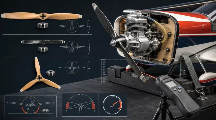
Quick answer: Start with the propeller range in the exact engine manual, then narrow it using the airframe manual, propeller manufacturer's application and RPM limit, available ground clearance, and a measured full-throttle tachometer check. Diameter, pitch, blade count, material and blade family are coupled variables. Do not assume that two propellers marked with the same diameter and pitch create the same load. Secure the aircraft, remain behind and outside the propeller plane, change one approved variable at a time, and discard any blade that is cracked, nicked, scratched, heat-damaged or altered.
Key principle: A propeller recommendation is a controlled starting envelope, not permission to ignore the airframe, blade family or measured loaded rpm.
What do propeller diameter and pitch mean?
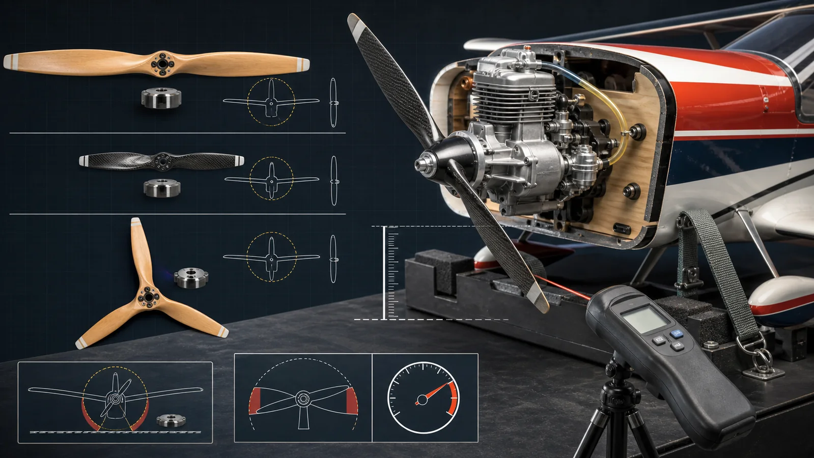
A model-aircraft propeller is commonly marked with two numbers. On APC propellers, the first number is diameter in inches and the second is geometric pitch in inches per revolution. A 16 x 8 is therefore 16 inches in diameter with a nominal 8-inch pitch. That notation is useful, but it is not a complete description of load or performance. Blade airfoil, chord, tip shape, material, stiffness, hub geometry, blade count and the maker's intended application also matter.
Diameter defines the size of the disk swept by the blades. Increasing diameter exposes more blade to the air and increases tip speed at the same engine RPM. It normally increases engine load substantially, but the exact change depends on the complete propeller design. Diameter also sets the physical clearance required between the rotating tip and the ground, cowl, fuselage, exhaust and nearby hardware.
Pitch is a geometric descriptor, not a guarantee that the airplane advances that distance on every revolution. Slip, blade airfoil and flight condition separate geometric pitch from actual travel. APC explicitly notes that measured pitch does not fully account for the effect of blade camber. A higher-pitch propeller can favor a higher theoretical advance speed, while a lower pitch can favor acceleration or static pull in a particular combination, but those are tendencies rather than universal outcomes.
That is why a size-only substitution is unsafe reasoning. A 16 x 8 electric propeller, a 16 x 8 glow-engine sport propeller and a 16 x 8 wood propeller may have different blade sections, inertia, hub requirements and RPM limits. Use the exact series named for the engine and application. The manufacturer's letters and family name are part of the specification.
Where should fuel model-airplane propeller selection start?
Begin with the exact engine manual. O.S. Engines describes its table as a starting point and says the best diameter and type depend on aircraft design, weight and flying purpose. Its current suggested-size page also warns that propellers of the same nominal size can behave differently between manufacturers. Saito manuals similarly provide engine-specific charts and pair them with tachometer and safety procedures.
Use the following order of authority:
- Engine manual: approved propeller sizes or ranges, operating RPM, hub and fastener arrangement, direction of rotation, starting method and any engine-specific warnings.
- Airframe manual: intended engine class, cowl and landing-gear clearance, spinner size, balance and center-of-gravity implications, noise constraints and flight purpose.
- Propeller documentation: internal-combustion approval, blade family, rotation, bore or bolt pattern, adapter procedure, RPM limit and inspection rules.
- Measured test: actual loaded RPM, reliable transition, temperature, vibration, fastener security and safe airframe behavior with one approved configuration.
If any of those documents conflict, do not average the numbers. Resolve the conflict with the engine, airframe and propeller manufacturers. The lowest applicable structural or operating limit remains a limit. A seller's generic statement such as “fits 30 cc engines” cannot replace the documentation for a particular engine, propeller family and airframe.
The EnginesDIY NGH GF150R5 five-cylinder radial engine illustrates why displacement alone is not enough. A large radial installation also brings a specific hub, cowl, cooling, vibration and airframe package. The radial engine model collection includes both running and display-oriented products, so verify that a product is actually approved to drive an aircraft propeller before applying flight-engine guidance.
How does each propeller variable change the decision?
| Variable changed | Likely effect to investigate | Required verification | Unsafe shortcut |
|---|---|---|---|
| Larger diameter | Usually more engine load, lower RPM, greater tip speed at a given RPM and less ground clearance | Engine range, propeller RPM limit, cowl and tip clearance, loaded RPM | Assuming one extra inch is a minor change |
| Higher pitch | Usually more load and greater nominal advance per revolution | Loaded RPM, acceleration, transition, temperature and airframe purpose | Choosing pitch from desired speed alone |
| More blades | More total blade area can raise load and may require a different diameter or pitch | Maker's multi-blade recommendation, engine RPM, hub and airframe clearance | Fusing separate propellers or copying a two-blade size |
| Different material or series | Changes mass, stiffness, inertia, blade shape, hub design and structural limit | Internal-combustion approval, bore or bolt pattern, RPM limit and balance | Treating electric, slow-flyer and glow propellers as interchangeable |
| Different manufacturer | Nominal size may stay the same while blade area and load change | Repeat tachometer, transition, vibration and clearance checks | Keeping the old needle setting and skipping the ground test |
| Spinner or adapter change | Can alter seating, clamping, blade-root clearance and rotating balance | Correct backplate, hub engagement, nut or bolt procedure and root clearance | Opening spinner slots until they touch or weaken the blade root |
Do not change diameter and pitch together unless the manual lists that exact alternative. If both change, a tachometer result cannot tell you which variable caused the difference. One-variable testing produces useful evidence and makes it easier to return to the last safe configuration.
Blade count deserves special caution. A three-blade propeller is not automatically equivalent to a two-blade propeller with the same printed size. More blades add area and alter the interaction between blades. Scale appearance or limited ground clearance may justify a multi-blade design, but the conversion needs a manufacturer or airframe recommendation and a fresh loaded-RPM test. Never bolt, glue or otherwise fuse complete propellers to create a higher blade count.
How do you use propeller RPM limits and a tachometer?
Two separate RPM questions must be answered:
- Is the engine operating inside the engine maker's approved loaded range?
- Is the propeller below the limit for that exact propeller family and diameter?
The answers come from different documents. The engine manufacturer tells you how the engine should be loaded and tuned. The propeller manufacturer sets the structural limit. The lower applicable boundary controls. Never use an unloaded engine RPM, estimated sound, advertised peak power RPM or a formula from another brand as proof that a propeller is safe.
APC provides a clear example of family-specific limits. Its page lists a suggested maximum of 190,000 ÷ diameter in inches for APC glow-engine Sport and Pattern propellers, while APC Slow Flyer, Thin Electric, folding, multirotor and racing families use different constants. The formula belongs only to the APC families named on that page. It is not a universal law for wood, carbon or another manufacturer's propellers.
Use a reliable optical tachometer from behind and outside the propeller plane. A product such as the CISON multifunction tachometer can be a discovery option, but confirm that its sensing method, range and setup match the engine and propeller being tested. A tachometer does not make an unsafe test safe; the aircraft still needs restraint, eye protection, a clear propeller arc and a competent operator.
Record propeller maker, complete part designation, diameter, pitch, blade count, material, ambient conditions, fuel, loaded maximum RPM, idle RPM and any abnormal vibration or transition. Density altitude and fuel affect the result, so a configuration tested in cool dense air may not produce the same RPM or mixture behavior on a hot high-altitude day. Repeat the check after a manufacturer change even when the stamped size appears identical.
What airframe fit and clearance checks are required?
A propeller can be acceptable for the engine and still be wrong for the airplane. Confirm all of the following with the aircraft supported in its real takeoff attitude and the engine unable to start:
- Ground clearance: measure at the most limiting attitude, including tail-up rotation, landing-gear compression and expected surface irregularity. Do not rely on a measurement with the airplane held level if takeoff or landing can move the disk closer to the ground.
- Cowl and fuselage clearance: rotate the propeller slowly through 360 degrees and check every blade. Include spinner backplate, fasteners, exhaust, fuel lines and any flexible cowling.
- Blade-root and spinner clearance: O.S. warns that spinner slots must not cut into or weaken blade roots. A spinner that requires unsafe slot enlargement is not a fit.
- Hub engagement: the propeller must seat on the correct drive washer, adapter, shaft or bolt pattern with the documented washers and fasteners. Do not stack improvised bushings.
- Rotation and blade orientation: confirm tractor versus pusher or reverse-rotation designation and install the blade face in the direction specified by its manufacturer.
- Airframe balance: a heavier propeller and spinner change rotating inertia and can affect the airplane's center of gravity. Recheck the aircraft manual's balance requirement before flight.
If the engine or propeller produces abnormal vibration, stop before interpreting performance. Follow the model-engine vibration guide to separate blade balance, spinner, adapter, mount, runout and bearing clues. Do not tune the carburetor around a mechanical vibration.
A controlled propeller selection and test workflow
- Identify the complete system. Record engine model and serial family, airframe, propeller brand and series, hub hardware, spinner, fuel, ignition and current operating history.
- Freeze the approved starting range. Copy the engine manual's recommended sizes and operating RPM. Note whether the table is for break-in, sport, aerobatic or scale use. Do not merge ranges from different engine models.
- Apply the airframe constraints. Remove choices that fail cowl, spinner, ground-clearance, noise or balance requirements. If the airframe manual specifies one propeller, begin there.
- Verify the exact propeller family. Confirm internal-combustion approval, rotation, material, bore or bolt pattern, adapter instructions and manufacturer RPM limit. Reject unknown or counterfeit parts.
- Inspect before mounting. Under good light, look and feel for cracks, nicks, scratches, softened areas, delamination, crushed wood fibers, enlarged holes, damaged hubs or previous repairs. If uncertain, discard the propeller.
- Balance and mount as documented. Use an appropriate balancer and the manufacturer's bore or adapter procedure. Clean mating faces. Tighten the correct nut or bolts with the specified tools and sequence; do not invent a torque value.
- Secure the test area. Restrain the airplane with a suitable stand or competent helper as permitted by the manual, remove loose objects, wear eye protection, keep spectators back, establish a shutdown method and remain outside the propeller plane.
- Start from a safe position. Use the maker's starting method. O.S. and Saito manuals warn against body parts and loose items in the propeller arc. Make carburetor adjustments only from the prescribed position, normally behind the rotating propeller.
- Measure instead of guessing. Warm the engine as directed, measure loaded RPM, check transition and observe vibration, temperature and fastener stability. Use the carburetor-tuning guide only within the engine manual's procedure.
- Stop and inspect. Shut down by the approved throttle or fuel method, wait for all rotation to stop, then inspect the propeller, hub, spinner, mount and fasteners. The overheating guide can help if the engine shows an abnormal thermal response.
- Change one approved variable. If testing another propeller within the documented envelope, alter diameter, pitch, blade count or manufacturer one at a time and repeat the complete record.
The first successful static test is not a blanket flight approval. Verify radio failsafe, range, structural condition, center of gravity and field rules. The Academy of Model Aeronautics Safety Code requires separation between powered model operations and spectators; local club and national rules may add stricter limits.
Propeller selection symptom table
| Observed result | Possible interpretation | Next safe action | What it does not prove |
|---|---|---|---|
| Loaded RPM below the engine's documented range | Excessive propeller load is possible, but mixture, fuel, ignition, compression or measurement error can imitate it | Stop, verify tachometer and engine health, then return to the documented starting propeller | That reducing pitch alone is always the correction |
| RPM exceeds the propeller-family limit | The propeller is outside its documented structural envelope | Shut down and select an approved propeller or operating combination | That a brief overspeed caused no damage |
| Good static RPM but poor flight acceleration | Airframe drag, pitch choice, mixture under flight load or another system may be involved | Land, preserve the configuration and review engine and airframe guidance | That a larger diameter is automatically required |
| New vibration after changing propeller | Balance, hub seating, spinner fit, blade damage or a different excitation frequency is plausible | Stop immediately and inspect the entire rotating stack | That the engine mount alone is defective |
| Tip approaches the ground during taxi | Static clearance was insufficient for gear compression or surface variation | Stop using that diameter on the airframe until the maker approves a safe alternative | That careful taxi technique removes the strike risk |
| Propeller nut repeatedly loosens | Incorrect seating, fastener procedure, wood compression, vibration or backfire may be involved | Stop; inspect hub, drive washer, spinner, fasteners and engine behavior against the manual | That stronger threadlocker is the correct fix |
When must a model-aircraft propeller be discarded?
Discard a propeller when its instructions or engine manual identify any unsafe condition. O.S. says split, cracked, nicked or otherwise unsafe propellers should not be repaired. Saito instructs users to discard propellers that are nicked, scratched, cracked or damaged. Those are conservative rules because centrifugal loading can turn hidden damage into sudden blade release.
Do not straighten, glue, weld, fill, sand away deep damage, add a new blade, drill an unapproved bolt pattern or combine two finished propellers. Master Airscrew publishes a dedicated safety instruction for its products, and APC provides product-family RPM limits and hub guidance. Follow the instructions for the exact part, not a generalized repair video.
Recent community questions show why this boundary matters. One builder described improvised blades made from household materials after earlier blades had broken, while another project considered joining two three-blade propellers to create a six-blade assembly. These posts establish a real information need, not technical permission. The safe answer is to use a purpose-built, documented propeller whose structure, hub and operating limit are known.
Before every start, clear loose gravel, tools, neck straps, clothing and wiring from the arc. Secure the model, verify failsafe and shutdown, wear eye protection, keep the face and body away from the blade plane and position spectators according to the strictest applicable manual, AMA, club or local rule. A warm glow engine may restart when turned over even without reconnecting the igniter, so treat the propeller as capable of movement until the fuel is isolated and the engine is safely cold.
Facts, inferences and unknowns
- Fact: O.S. and Saito publish engine-specific starting propeller ranges and require practical or measured verification rather than size-only selection.
- Fact: APC publishes different RPM limits for different APC propeller families; its glow-engine formula is not the limit for every propeller.
- Fact: nominal diameter and pitch do not fully describe blade area, airfoil, inertia, hub geometry or structural limit.
- Fact: O.S. and Saito instruct operators to discard damaged propellers and keep people and loose objects away from the propeller arc.
- Inference: a lower-than-expected loaded RPM can indicate excess propeller load, but it can also result from engine tune, fuel, ignition, compression, weather or tachometer error.
- Inference: a multi-blade conversion often requires reducing another load variable, but no universal “one inch smaller” rule applies across engines and propeller designs.
- Unknown: without the exact engine, airframe, propeller family, conditions and measured loaded RPM, a safe final propeller cannot be selected from displacement alone.
For broader engine discovery, use the model engine kits collection and starting and ignition accessories, then verify whether the exact product is a flight powerplant, a bench-running miniature engine or a display model. These categories are not substitutes for the product manual.
Frequently asked questions
Can I use a larger-diameter propeller with less pitch?
Only when the engine and airframe documentation permit that combination. A larger diameter can increase load and tip speed while reducing clearance; lower pitch does not automatically cancel those effects. Measure loaded RPM and stay within the exact propeller-family limit.
Are electric and glow-engine propellers interchangeable?
Not by default. Propeller families can differ in blade shape, hub, material and RPM limit. APC, for example, identifies Sport propellers for internal-combustion use and Electric propellers for electric motors. Use only the application approved by the manufacturer.
What does a 16 x 8 propeller mean?
For manufacturers using the common inch convention, it usually means 16-inch diameter and 8-inch nominal geometric pitch. Confirm the maker's nomenclature. The marking does not state blade area, airfoil, material, number of blades or operating limit.
Can I replace a two-blade propeller with a three-blade propeller?
Yes only within a documented engine and airframe conversion. The same printed diameter and pitch can overload the engine because the third blade adds area. Use a maker-recommended starting size, verify hub and clearance, and measure loaded RPM.
How much ground clearance does an RC airplane propeller need?
Use the airframe manufacturer's minimum and the rules for the operating field. Measure in the most limiting realistic attitude with landing-gear compression and uneven ground considered. There is no single safe clearance for every aircraft and surface.
Can I repair a small nick in a model-aircraft propeller?
Follow the exact propeller manufacturer's rule. O.S. and Saito direct users to discard nicked or otherwise damaged propellers rather than repair them. If the damage status is uncertain, remove the propeller from service.
Why did the engine RPM change with another propeller of the same size?
Nominal size does not fix blade area, airfoil, stiffness, surface finish, hub shape or manufacturing tolerance. O.S. notes that properties vary between manufacturers. Treat a brand or series change as a new configuration and repeat the tachometer and safety checks.
Conclusion
Safe propeller selection is an evidence chain. The engine manual provides the starting envelope, the airframe removes combinations that do not physically or operationally fit, the propeller maker defines application and structural limits, and a controlled tachometer test shows the actual loaded result. Keep diameter, pitch, blade count, material and family separate in your records. If the documentation is missing, the propeller is damaged, clearance is uncertain or the measured RPM violates any limit, stop and resolve that uncertainty before flight.
References
- APC Propellers - RPM Limits
- APC Propellers - Propeller Nomenclature and Application Types
- O.S. Engines - MAX-120AX Instruction Manual
- O.S. Engines - Suggested Propeller Sizes
- Saito Engines / Horizon Hobby - Gas Engine Operating Manual
- Academy of Model Aeronautics - Safety Handbook
- Master Airscrew - Propeller Safety Instruction
Leave a comment