

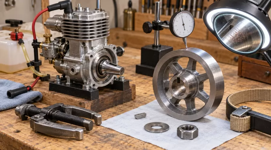
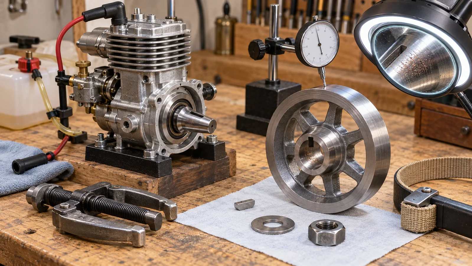
Quick Answer
A flywheel key should index the flywheel, but it should not automatically be treated as the only part carrying torque. On many tapered-shaft designs, clean mating tapers and the specified clamp load create the holding friction. A damaged key can shift ignition timing, yet a repeatedly damaged key may be evidence of poor taper contact, contamination, inadequate clamping, a loose fastener, impact damage or incompatible parts.
The T-K-C evidence record separates taper contact, key condition and clamp evidence. T records the condition and contact of the mating tapers; K records the key, slots and angular location; C records the washer, nut or bolt, specified tightening procedure and evidence of loosening. Diagnose all three before filing a key, applying compound or ordering a crankshaft.
Key takeaways
- A key that has moved or sheared can alter the relationship between the crankshaft and flywheel-mounted ignition trigger, but timing symptoms still require ignition and mechanical checks.
- Visible contact only around one edge of a taper suggests poor seating, burrs, mismatch or distortion; it does not prove the key is the root cause.
- Never hammer a flywheel or lever against thin crankcase surfaces. Use the puller and support points specified for the engine.
- Do not transfer torque values, lubricants, threadlockers, lapping practices or retaining compounds between engines. The joint design and fastener condition determine the procedure.
- Measure runout at defined surfaces and more than one axial station. A dial indicator cannot by itself distinguish a bent shaft from an eccentric or contaminated hub.
- Replace cracked, distorted or badly fretted rotating parts. A filed key or adhesive cannot restore missing geometry.
How the taper, key and clamp work
The taper creates a self-centering friction joint
A matching shaft and hub taper converts axial clamp force into normal force around the conical contact area. When the surfaces are compatible, clean and seated as designed, that normal force produces friction that resists relative rotation. The taper also centers the flywheel. This is why a correctly assembled joint can transmit much more than the small cross-section of a Woodruff or parallel key might suggest.
If a burr, chip, raised impact mark, corrosion, old compound or incompatible taper prevents full seating, contact concentrates in a small area. The flywheel can rock microscopically under combustion, starter or propeller impulses. Fretting debris, polished patches and a key hammered against one side of its slot then appear. Replacing only the key may briefly restore the angular position without correcting the failed joint.
The key establishes angular location
The key aligns the flywheel or trigger feature with the crankshaft. On an ignition engine, that relationship may determine when a magnet, pickup, cam or trigger passes its sensor. A partly sheared or displaced key can therefore produce hard starting, kickback, weak power or apparently inconsistent ignition timing. Briggs & Stratton specifically includes a sheared flywheel key among the checks for timing trouble.
That does not make every no-start a flywheel fault. Spark energy, plug condition, coil air gap, wiring, compression, fuel mixture and valve events can create similar symptoms. Use the model-engine ignition timing and BTDC guide to verify reference marks and measurement method before moving the flywheel.
The clamp maintains contact
A nut, bolt, washer, collet or other retainer supplies and maintains axial force. Wrong washer orientation, damaged threads, bottoming before the hub is clamped, dirt under the washer, an incompatible replacement flywheel or an unauthorized lubricant can change the achieved clamp load. A torque wrench reading is not direct proof of joint force when threads are damaged, contaminated or treated differently from the manual.
Threadlocker and retaining compound have different jobs. The threadlocker and retaining-compound guide explains why neither product should be selected by color alone. Unless the exact engine documentation calls for a named product and preparation, adding adhesive can hide the evidence, alter friction and make later removal unsafe.
Symptom-to-evidence matrix
| Observation | Possible T-K-C cause | Other causes to exclude | Next evidence |
|---|---|---|---|
| Sudden kickback or timing shift | Key displaced; hub slipped on taper; clamp lost | Incorrect timing procedure, pickup movement, reversed rotation, valve timing | Reference-mark comparison, key inspection, taper witness marks, fastener condition |
| Flywheel repeatedly loosens | Poor taper contact, wrong parts, thread/washer damage, insufficient specified clamp | Driven-load imbalance, impact start, bearing movement, cracked hub | Contact pattern, part numbers, axial seating, threads, washer stack and runout |
| Vibration after flywheel work | Hub not seated, key standing proud, debris, distorted flywheel | Propeller imbalance, loose mount, bent crankshaft, damaged bearing | Runout at hub and rim, mounting-face cleanliness, shaft check with flywheel removed |
| Key edge peened or smeared | Relative rotation under load, slot damage, incorrect key, poor taper grip | Damage created during impact removal or forced assembly | Key dimensions from manual, slot edges, fretting debris, tool history |
| Indicator changes when nut is tightened | Hub cocking, dirt, washer interference, nonmatching taper | Indicator base movement or flexible measuring surface | Repeat at several clamp stages only if the manual permits; verify stable datum |
If vibration is the main complaint, use the propeller, mount, runout and bearing vibration workflow. If the flywheel is part of a starter drive, first follow the starter and one-way-bearing troubleshooting guide. These branches prevent a flywheel from becoming the default explanation for every rotating fault.
The safe T-K-C diagnostic workflow
- Make the engine incapable of starting. Stop and cool it. Isolate fuel, ignition, glow power and batteries. Remove a propeller or driven load only by the manufacturer's procedure. Secure the engine without distorting its crankcase.
- Identify the exact engine and joint. Record model, revision, crankshaft and flywheel part numbers, rotation direction, ignition architecture, key type, washer stack and retainer. Similar-looking tapers are not proof of compatibility.
- Record the symptom before disassembly. Note when it began, recent impacts or service, starting direction, timing readings, vibration, noise and whether the retainer was found loose. Photograph reference marks and the exposed stack.
- Check external movement. With the engine safe, look for hub rocking, axial movement, witness dust, cracked spokes, damaged starter features or contact with covers. Do not keep rotating a visibly cracked flywheel.
- Measure assembled runout when safe. Mount a dial indicator on a rigid reference. Mark the angular position and measure at the manual's specified surface. Repeat to separate a stable high spot from random movement.
- Remove only with the correct puller. Briggs advises using a flywheel puller and not striking the flywheel. Protect the shaft end exactly as the tool instructions require. Never wedge against a thin crankcase flange or coil mount.
- Build the T record. Before cleaning, photograph fretting, polished arcs, rust, transferred metal and high-contact patches. Then inspect the full shaft and hub tapers under good light and magnification.
- Build the K record. Inspect both sides and ends of the key, its height relative to the shaft, and both slots. Look for shear steps, mushroomed edges, cracks, rolled slot lips or evidence that the key stood proud and prevented seating.
- Build the C record. Inspect threads, washer faces, nut or bolt seating, locking method and any bottoming marks. Compare every part and preparation step with the current manual.
- Measure the shaft separately. If runout was abnormal, indicate a specified crankshaft surface with the flywheel removed. This separates shaft bend or bearing movement from flywheel eccentricity.
- Choose repair, replacement or stop. Cosmetic staining may be cleanable if the manual permits; raised metal, deep fretting, cracks, distorted slots or nonmatching geometry require authoritative limits or replacement.
- Reassemble exactly once. Use the specified key, surface condition, washer order, fastener treatment and tightening method. Verify timing, free rotation, clearance and runout before restoring fuel or ignition.
Runout, contact and timing checks
Separate shaft runout from flywheel runout
One indicator reading at the flywheel rim combines shaft condition, bearings, taper seating, hub geometry and rim geometry. Measure at the manual's datum whenever one is specified. If safe and authorized, compare the hub near the taper with a farther radial surface, then measure an appropriate shaft surface after removal. A high spot that follows the shaft suggests a different branch than a hub that changes after each installation.
Do not invent a universal acceptable value. A small high-speed rotor, a scale stationary engine and a large low-speed model have different mass, speed, bearing and ignition requirements. The measuring setup must also be stiff enough that hand pressure does not move the base. Record indicator direction, contact point, resolution, support and temperature so the result can be repeated.
Read contact evidence before altering it
Good-looking shiny metal is not automatically full contact. Uniform circumferential evidence is different from a narrow bright ring, one-sided polish or scattered high spots. Fretting often appears as dark oxide, fine reddish or black debris and repeated small-motion marks. A key battered on one flank supports relative movement but does not tell whether the first failure was poor clamping, mismatch, impact or key error.
Do not file the taper, deepen a keyway or lap two unknown parts together merely to improve the visual pattern. These actions permanently change geometry and may move the flywheel axially, changing sensor clearance, cover clearance or starter alignment. Kohler and Briggs procedures emphasize inspecting damage and replacing defective parts; exact model instructions decide what surface correction, if any, is permitted.
Verify ignition timing as a system
After a key or flywheel fault, restore the original reference relationship before judging ignition. Confirm the true crank position using the specified method, verify the trigger or magnet orientation, and inspect sensor mounting. A slipped hub can explain a new timing error; it cannot explain weak spark caused by a damaged coil or bad electrical connection.
For an engine that still starts poorly, use the compression and leak-down guide to separate sealing from ignition. Four-stroke owners should also verify valve events rather than advancing ignition to mask a cam or valve problem.
Repair, replacement and buying decisions
| Evidence | Decision | Why |
|---|---|---|
| Loose dirt or removable residue; no raised metal or cracks | Clean only by the specified method, then re-inspect | Surface preparation affects seating and friction; the manual controls solvent and final condition |
| Correct new key but damaged slot lip or repeated shearing | Stop and inspect hub, shaft, contact and clamp stack | The repeated key failure is evidence that another part of T-K-C may be wrong |
| Crack, distorted hub, deep fretting, enlarged slot or missing taper geometry | Replace or obtain a qualified dimensional repair | Adhesive or a larger key cannot restore concentricity and fatigue strength |
| Unknown flywheel/crank pairing | Verify part numbers and taper specification before assembly | Similar angle or apparent seating does not prove full-area contact or axial position |
| No manual or reliable parts data | Pause and obtain documentation or manufacturer support | Torque, washer, key and surface treatment cannot be safely inferred from engine size |
When selecting a replacement engine or kit, serviceability matters. Ask whether the maker publishes exploded views, key and fastener part numbers, ignition references, puller requirements and replacement flywheel availability. Browse model engine kits for architecture context and model-building workshop tools for measuring and puller options, but verify fit against the exact engine documentation before purchase.
Why manufacturer procedures differ
Cross-manufacturer advice must be read in context. Briggs and Honda documentation emphasizes clean mating tapers; Honda explains that dirt can prevent secure contact and transfer excessive load to the key. A Rotax service bulletin for a named aircraft-engine installation specifies its own degreasing and compound procedure. That does not mean compound belongs on every model-engine taper. It means the engineering instruction for the exact joint controls.
The same caution applies to torque. Thread size alone does not set a safe value. Fastener grade, pitch, washer, lubrication, locking method, hub stiffness and intended preload all matter. Do not copy a value from a full-size lawn engine, an aircraft engine or a forum post into a miniature engine.
Safety and limits
- A flywheel stores energy. Do not run a cracked, visibly loose or rubbing flywheel, and keep people out of its plane of rotation.
- Never hold a flywheel by energizing the starter or ignition. Use the approved locking method and removal tool.
- Do not strike cast flywheels, magnets or crankshaft ends. Impact can crack components, damage bearings and magnetize debris.
- Do not use abrasive paste near open bearings, seals or engines unless a manufacturer procedure specifically requires it and includes complete cleaning.
- This guide provides a diagnostic framework, not a universal torque, taper angle, key size, runout tolerance or adhesive specification.
Frequently Asked Questions
Does the flywheel key carry all engine torque?
Not necessarily. In many tapered joints, the specified clamp force and taper friction resist rotation while the key establishes angular location. The exact design controls, so do not assume the key is either purely an index or the sole torque member without the manual.
Can a partly sheared flywheel key change ignition timing?
Yes, when the ignition reference is tied to flywheel position. A shifted key or slipped hub can move the trigger relationship. Verify true crank position and the complete ignition system before replacing parts.
Why does a new key shear again?
Repeated damage suggests unresolved taper contact, incorrect key or flywheel, damaged slots, lost clamp load, impact starting or excessive driven-load shock. Inspect the whole T-K-C record instead of installing another key.
Should I lap a model-engine flywheel taper?
Only if the exact manufacturer or qualified repair procedure authorizes it. Lapping changes axial seating and can contaminate bearings. It can also hide a mismatched taper instead of correcting it.
Should the taper be dry or use retaining compound?
Follow the exact engine instruction. Some manuals require clean dry surfaces; particular designs may specify a named compound and preparation. Never transfer that instruction between engines.
How do I remove a stuck flywheel safely?
Use the correct puller and approved shaft protection/support method. Do not hammer the flywheel or lever against thin crankcase, coil or cover surfaces.
How can I tell whether the crankshaft or flywheel is bent?
Measure runout at specified hub and shaft datums with a rigid indicator setup. Comparing the assembled flywheel with an appropriate shaft surface after removal helps separate the sources, but the manual's limits still decide serviceability.
Can I file a key so the flywheel seats farther?
Do not alter it by guesswork. A proud or wrong key may block seating, but a correctly specified key and undamaged slots should be verified first. Filing can shift timing and remove the evidence needed to diagnose incompatible parts.
Conclusion
A damaged flywheel key is a clue, not a complete diagnosis. Preserve the evidence, separate taper contact from key location and clamp condition, and measure runout before changing geometry. The T-K-C record turns a repeated loose-flywheel problem into a controlled decision: clean and reassemble by the exact manual, replace damaged parts, or stop until authoritative specifications are available.
References
- Briggs & Stratton: Inspecting the flywheel and key
- Briggs & Stratton: Ignition system theory and testing
- Kohler: HD Series Service Manual
- Honda: Common Service Manual (archived copy)
- Rotax: Service Bulletin SB-912-026 / SB-914-014
- O.S. Engines: O.S. Speed tools
- FAA: Aviation Maintenance Technician Handbook—Powerplant
Leave a comment