

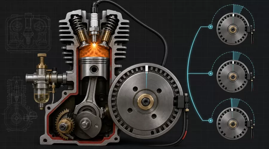
Quick answer: Set model-engine ignition timing from the exact manufacturer's specification, not from a generic angle or the visible Hall-sensor position. First find true top dead center on the compression stroke, confirm normal rotation, mark the prescribed BTDC position, then verify when the ignition module actually triggers. A static test establishes the baseline; a timing light can reveal the running timing and any electronic advance. Stop if the engine kicks back, knocks, overheats, or behaves unpredictably.
Key principle: Timing is a measured relationship, not a sensor position. The relationship includes the crankshaft reference, compression stroke, direction of rotation, trigger geometry, ignition-module logic, and spark event.
What does model-engine ignition timing mean?
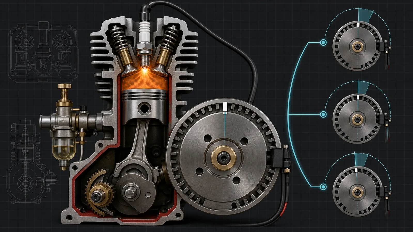
Ignition timing is the crankshaft position at which the spark is commanded relative to top dead center. In a four-stroke gasoline engine, the relevant event is near the end of the compression stroke, when both valves should be closed and the compressed air-fuel charge is ready to burn. “BTDC” means before top dead center in the engine's normal direction of rotation.
NASA's explanation of the Wright 1903 engine makes the central point: combustion takes a finite amount of time, so the ignition event does not normally occur exactly at the top of piston travel. Advance starts the combustion process earlier relative to piston position. The correct amount depends on combustion-chamber shape, compression, fuel, mixture, speed, load, temperature, and the ignition system. That is why an angle copied from another engine is not a safe setup value.
Spark timing is different from valve timing. Valve timing describes when the intake and exhaust valves open and close; ignition timing describes when the spark occurs. A model can have correctly aligned cam gears yet incorrect spark timing, or the reverse. If valve events are uncertain, diagnose them separately with the miniature four-stroke valve timing and lash guide.
Why the visible Hall sensor does not tell the whole story
Many miniature gasoline engines use a magnet or steel trigger on the flywheel and a Hall sensor connected to a CDI or electronic igniter. The sensor's physical centerline may not equal the spark angle. The module can trigger on one edge of the magnetic field, include a starting retard, apply an RPM-dependent advance curve, or introduce a fixed electrical delay. Magnet polarity, sensor orientation, trigger width, rotation direction, and mounting geometry also affect the event.
O.S. Engines warns owners of its GT120T not to move the rotation sensor because it is installed at the engine's optimum position. That is model-specific manufacturer guidance, but the broader lesson transfers: never loosen a factory-set trigger merely because its bracket does not appear to line up with a mark. Consult the exact manual and measure the event.
Advanced, correct, and retarded ignition timing
| Timing condition | What happens | Possible observations | Important caution |
|---|---|---|---|
| Too advanced | Pressure rises too early while the piston is still approaching TDC | Kickback, harsh firing, metallic knock, difficult starting, abnormal heat, mechanical stress | Do not keep advancing until it “sounds powerful” |
| Manufacturer baseline | Combustion phasing matches the engine's documented design and ignition system | Repeatable starting and stable running when fuel, compression, load, and cooling are correct | A good baseline is not proof that every other system is healthy |
| Too retarded | Pressure develops later in the expansion stroke | Weak power, lazy response, hotter exhaust, incomplete burn, possible afterfire | These symptoms also have fuel, plug, exhaust, and compression causes |
These are diagnostic patterns, not a substitute for measurement. The U.S. Department of Energy explains that normal combustion begins at the spark plug and a flame travels through the charge. Knock occurs when the unburned end gas autoignites under sufficient temperature, pressure, and time, producing the familiar ping and potentially damaging pressure behavior. Michigan Technological University testing found that greater spark advance increased knock intensity under otherwise maintained test conditions. That controlled result does not create a universal model-engine limit; it explains why “advance it until it knocks” is an unsafe bench method.
Checks to complete before changing ignition timing
- Find the exact manual. Match the engine model, ignition module, sensor, flywheel, and rotation direction. Similar-looking CDI units can have different curves and voltage requirements.
- Confirm the fuel and oil. Wrong fuel, stale fuel, incorrect oil content, or a lean carburetor setting can mimic or amplify timing symptoms.
- Verify compression. Low compression, valve leakage, ring leakage, or a head leak can make a correctly timed engine hard to start. Use the model-engine compression and leak-down guide before compensating with timing.
- Check the spark system. Confirm the specified plug, plug gap, battery voltage, ground, cap connection, kill-switch state, and sensor wiring. Briggs & Stratton recommends testing the ignition system methodically and notes that timing faults in flywheel-magnet small engines can follow flywheel-key damage.
- Inspect the mechanical reference. A loose flywheel, shifted key, slipping trigger hub, damaged bracket, or ambiguous hand-drawn mark can make every later measurement wrong.
- Remove abnormal load. A binding drivetrain, unsuitable propeller, tight new engine, or seized accessory can cause slow cranking and heat that resembles excessive advance.
Start from a complete matched system. The site's model-engine ignition electronics and starting and ignition accessories categories show the range of components available, but category placement does not guarantee interchangeability. Confirm plug thread, sensor type, trigger polarity, module voltage, cylinder count, firing arrangement, and advance behavior.
A measurement-first static timing workflow
This workflow describes the logic, not a universal service procedure. The engine manual controls. If the manufacturer says the sensor is factory-set or the module should not be energized during hand rotation, do not override that instruction.
Step 1: Make the engine safe
Remove fuel from the immediate work area, secure the engine, disconnect the starter, and remove any propeller or driven component if the manual permits. Keep the ignition disabled until the procedure requires a spark test. O.S. warns that a gasoline model engine can fire unexpectedly when cranked and that the plug, cap, high-tension lead, and energized module can deliver a shock. Never hold an exposed plug in your hand.
Step 2: Confirm normal rotation
Mark the normal direction before finding BTDC. The FAA maintenance handbook instructs technicians to approach the prescribed timing position in the normal direction of rotation. This removes gear, key, and linkage backlash from the final approach. If you overshoot, back away sufficiently and approach again in the normal direction rather than creeping backward to the mark.
Step 3: Identify the compression stroke
On a four-stroke engine, the piston reaches top dead center twice: after compression and after exhaust. Both valves should be closed on compression. The FAA method identifies the compression stroke by pressure developing at the spark-plug opening before the piston reaches the prescribed firing position. Use a safe non-marring method appropriate to the miniature engine; never insert a hard tool that can jam against the piston.
Step 4: Establish true TDC
A piston moves very little near the top of its travel, so the highest visible position alone is imprecise. Prefer the manufacturer's crank mark, a suitable piston-position indicator, or a degree-wheel method that brackets equal piston positions on both sides of TDC. Split the two readings to locate the midpoint. Do not force the engine against a stop, and do not use a piston stop on an engine or plug angle for which it is unsafe.
Step 5: Mark the prescribed BTDC position
Once true TDC and normal rotation are known, use a degree wheel or the manufacturer's marks to locate the specified firing position before TDC. Record the pointer, flywheel mark, reference diameter, and direction. A measured arc length is valid only for the exact diameter on which it was calculated; degrees are the more portable record.
Step 6: Detect the trigger event safely
Follow the ignition manufacturer's test method. Depending on the system, this may use an approved timing indicator, a safely grounded plug observed without touching it, or a module diagnostic signal. Rotate through the firing position in the normal direction and note the first consistent event. Repeat the approach several times. If readings scatter, investigate trigger gap, loose mounting, battery condition, magnet position, wiring, and crankshaft play before adjusting the sensor.
Step 7: Adjust only if the manual authorizes it
Make a small controlled change, tighten the mounting hardware to the specified torque, and repeat the measurement. Do not enlarge slots, reverse a magnet, file a key, or substitute an ignition module to obtain a desired number. A matched kit such as the RETROL HM01 CDI igniter and spark-plug set or a model-specific SEMTO starter and ignition kit still requires verification against its current manual and intended engine.
Dynamic timing verification with a timing light
A static check proves where the module triggers during slow rotation. It may not show the running spark angle. Electronic CDI systems can retard the spark for starting and advance it as RPM increases. A compatible inductive timing light aimed at a clear flywheel reference can reveal that behavior, but miniature engines present unusual scale, access, high voltage, rotating parts, and stroboscopic hazards.
- Use only a timing light and pickup compatible with the ignition lead and module.
- Secure the engine and every wire so nothing can enter the flywheel, coupling, belt, fan, or propeller arc.
- Begin at the manufacturer's safe baseline and the lowest prescribed test condition.
- Observe the timing mark without leaning over the rotating plane.
- Record RPM and load with the angle. A model-engine tachometer can provide RPM context when it is compatible, but it does not establish ignition timing by itself.
- Compare the measured curve only with documentation for the exact module and engine.
A timing mark that appears to jump can reflect true trigger instability, a loose flywheel, electrical noise, multiple sparks, a wasted-spark event, timing-light incompatibility, or an observation error. Do not immediately move the sensor. Stop, isolate the cause, and repeat the measurement.
Diagnosing timing symptoms without guessing
Kickback or starter reversal
Kickback makes excessive advance plausible because combustion pressure may oppose the rising piston, but also check rotation direction, cylinder assignment, trigger polarity, flywheel position, and whether the engine is actually on the compression stroke. Low starter voltage or excessive mechanical load can produce similar slow or abrupt motion. Do not keep energizing the starter until something breaks.
Weak power and hot exhaust
Retarded timing is one possible cause, because useful pressure develops later, but a rich mixture, restricted exhaust, weak spark, low compression, late valve timing, and excessive load can look similar. Return fuel and ignition to documented baselines and change one variable at a time.
Knock, harsh firing, or rapid heat rise
Stop the run. Excessive advance, unsuitable fuel, a lean mixture, high load, deposits, excessive compression, and inadequate cooling can interact. Use the model-engine overheating and cooling guide to examine the thermal path. Never treat silence after retarding the sensor as proof that the root cause is solved.
Spark exists but the engine will not start
A visible spark outside the cylinder proves neither correct timing nor adequate spark under compression. Verify compression TDC, actual trigger position, plug condition, fuel delivery, mixture, compression, and valve state. The model-engine no-start guide provides a broader diagnostic tree.
Changed behavior after a flywheel or ignition repair
Recheck the key, taper, hub, trigger magnet, sensor bracket, wire routing, ground, plug cap, and module part number. Briggs & Stratton identifies a sheared flywheel key as a common timing cause on its small engines. Your miniature engine may use a different mechanical design, so inspect its own drawings rather than assuming the same failure mode.
Choosing an ignition system for a miniature gasoline engine
Before buying, identify the cylinder count, firing order, spark-plug type and thread, battery-voltage range, sensor type, trigger magnet, normal rotation, static timing requirement, starting-retard behavior, advance curve, maximum RPM, grounding method, kill-switch connection, and high-tension lead layout. An ignition set advertised for a V-twin may fire simultaneously, sequentially, or by a particular crank arrangement; the name alone is insufficient.
Use complete engine pages such as the CISON FG-VT9 V-twin model and L100 single-cylinder gasoline engine only as examples of different architectures. Confirm what is included, what is pre-adjusted, and which manual applies to the current version. Supplier statements about compatibility are supplier claims until verified against part numbers and documentation.
Limits, safety, and what remains unknown
- Fact: combustion takes finite time; spark timing is referenced to crank position; excessive advance can increase knock risk; repeatable timing requires a defined reference and direction.
- Reasonable inference: checking reference, stroke, direction, trigger, spark, and advance in sequence reduces ambiguous diagnoses on miniature engines.
- Supplier claim: module compatibility, factory sensor position, voltage, plug, timing angle, and advance curve must come from the exact product maker.
- Unknown without documentation or controlled measurement: the safe BTDC value, trigger gap, maximum RPM, dynamic curve, and acceptable timing variation for an unspecified engine.
Operate fuel-burning model engines only in a controlled, ventilated area appropriate to the equipment. Secure the engine and fuel system, keep ignition sources away from spilled fuel, use eye and hearing protection, and keep bystanders outside the rotating-part zone. The Academy of Model Aeronautics emphasizes controlled operating areas and separation from spectators. A strobe can make a rotating flywheel or propeller appear stationary; never trust the visual illusion.
Frequently asked questions
What is the correct ignition timing for a model engine?
There is no universal value. Use the exact engine and ignition manufacturer's specification, measured from true TDC on the compression stroke in the stated direction of rotation.
Does the Hall sensor position equal the BTDC angle?
Not necessarily. Trigger edge, magnet geometry, sensor orientation, module delay, starting retard, and electronic advance can make the actual spark event differ from the sensor centerline.
How do I know I am on the compression stroke?
On a four-stroke engine, both valves should be closed and pressure should build as the piston approaches TDC. Follow the manual's method and use a safe piston-position procedure.
Can I set ignition timing by sound?
No. Sound is affected by load, exhaust, fuel, mixture, mechanical clearance, and structure. Use the documented marks and an approved static or dynamic measurement method.
Why does my model engine kick back when starting?
Excessive advance is one possibility, but wrong rotation, wrong cylinder or stroke, trigger polarity, low starter voltage, or mechanical binding can also cause abrupt starting behavior. Stop and verify the full setup.
Should I advance timing for more power?
Do not advance beyond the documented setting as a casual power adjustment. Excessive advance can increase knock and mechanical stress, while the safe limit changes with fuel, mixture, compression, temperature, speed, and load.
Conclusion
Reliable model-engine ignition timing begins with references, not guesses. Identify compression TDC, confirm normal rotation, mark the manufacturer's BTDC position, measure the trigger event, and verify running behavior only with compatible tools and controlled conditions. If the engine still starts poorly or runs hot, treat timing as one branch alongside fuel, spark quality, compression, valve events, load, and cooling. That disciplined sequence protects both the engine and the person testing it.
References
- NASA Glenn Research Center, Timing System
- FAA, Aviation Maintenance Technician Handbook - Powerplant, Chapter 4
- Briggs & Stratton, Ignition System Theory and Testing
- O.S. Engines, GT120T Gasoline Model Engine Manual
- Michigan Technological University, Effect of Spark Advance and Fuel on Knocking Tendency
- U.S. Department of Energy, Co-Optima Spark-Ignition Engine Webinar Transcript
- Academy of Model Aeronautics, Safety Program Handbook
- To compare operating methods and assembly levels after diagnosis, browse model engine kits.
Leave a comment