

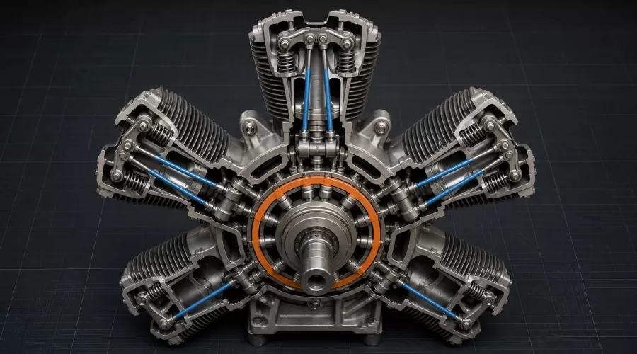
Quick answer: A single-row radial engine usually uses a concentric cam ring rather than a separate camshaft running beside the cylinders. Intake and exhaust lobes on two tracks lift rollers or tappets; each tappet moves a pushrod, the pushrod rotates a rocker arm, and the rocker opens a valve. The ring is geared to the crankshaft at a reduced speed, sometimes in the same direction and sometimes in the opposite direction. That relative motion lets a small number of lobes schedule valves for every cylinder. The exact lobe count, drive direction, clearance and timing procedure are engine-specific.

Key takeaways
- A cam ring is concentric with the crankshaft; it is not the same component as the master rod or crankshaft.
- A single-row radial commonly places intake lobes on one track and exhaust lobes on another.
- The cam ring's speed and direction relative to the crankshaft determine when each tappet meets a lobe.
- A radial engine does not need one cam lobe per cylinder because the cam ring and crankshaft move relative to each other.
- Valve clearance changes the usable motion between cam, tappet, pushrod, rocker and valve, but it does not repair incorrect internal gear timing.
- Observe and record before adjusting. Use the maker's cold-clearance, cylinder-order and timing procedure for the exact engine.
Why a radial engine uses a cam ring
A conventional inline or opposed four-stroke engine can place a camshaft parallel to the crankshaft and distribute lobes along its length. A radial engine arranges cylinders like spokes around one crankcase. A long straight camshaft cannot sit equally close to every cylinder, so a concentric ring provides a compact common path.
The FAA Powerplant Handbook illustrates a ring around the crankshaft with cam rollers, tappets, pushrods, rocker arms, valve springs and two cam tracks. As a lobe passes a roller, the tappet moves outward. That linear movement travels through a pushrod to a rocker at the cylinder head. The rocker converts it into valve lift. Once the lobe passes, the spring closes the valve and returns the linkage.
This architecture is separate from the crank mechanism. The master and articulating rods distribute piston force around one crankpin. The cam ring distributes valve events around the cylinder row. Understanding both systems explains why a radial engine can share one crank throw and one valve-scheduling device without making all cylinders move or fire together.
Follow the five-part motion chain
| Part | Motion | What to observe | Common misunderstanding |
|---|---|---|---|
| Cam ring and track | Slow rotation around the crank axis | Intake and exhaust lobe tracks, drive gear relationship | The ring does not rotate at crankshaft speed |
| Roller or tappet | Rises and falls on the lobe profile | Smooth contact and return | A stopped tappet is not automatically stuck; it may be on the base circle |
| Pushrod | Reciprocates outward and inward | Straight movement, seated ends and undamaged tube | Pushrods do not set the firing order by themselves |
| Rocker arm | Pivots | Consistent travel, intact adjuster and locknut | Visible rocker travel alone does not prove correct timing |
| Valve and spring | Opens, then returns to its seat | Full smooth return and model-specified clearance | A nearly closed valve can still leak compression |
The general cam-and-follower principle is easy to see in NASA Glenn's timing-system explanation: the cam radius changes under the follower, creating controlled motion at a specific crank relationship. A radial cam ring applies that principle around a circle. One track works intake events and another works exhaust events. The lobe flanks include ramps so the mechanism takes up motion progressively rather than striking the valve gear abruptly.
Opening is only half the event. The valve spring must close the valve, the rocker must return, the pushrod must remain seated and the tappet must follow the descending lobe. A weak spring, tight guide, bent pushrod, damaged roller or incorrect clearance can change what the observer sees even if the ring itself is correctly timed.
Why the cam ring has fewer lobes than cylinders
Looking at a five-, seven- or nine-cylinder radial often produces a reasonable question: why is there not one intake and one exhaust lobe for every cylinder? The answer is relative motion. The cylinders and tappet guides are fixed to the crankcase. The crankshaft rotates at engine speed. The geared cam ring rotates more slowly, and its direction can be selected so each tappet encounters a lobe at the required interval.
Suppose the crankshaft advances while the cam ring also moves. The angular closing rate between a fixed tappet position and the next lobe is not simply the ring speed viewed alone. Gear ratio, ring direction and lobe spacing work as one system. That is why a lobe-count table cannot be separated from its specified direction of rotation. The FAA handbook shows that rings with different lobe counts and directions can serve different odd cylinder counts.
The odd-cylinder firing sequence explained in why four-stroke radials use an odd number of cylinders is related but not identical. Firing order describes when cylinders produce power. Valve timing describes when each cylinder admits charge and releases exhaust. Ignition timing describes when the spark or ignition event begins. These schedules must agree, but changing one adjustment does not automatically correct the others.
What a radial model can honestly demonstrate
A transparent or hand-rotated radial assembly can make the architecture easier to understand than a drawing. Start at the cam track and watch one complete cylinder cycle: intake rocker moves, both valves close for compression, the piston passes the firing position, and the exhaust rocker moves near the end of the power cycle. Then follow the next cylinder in the specified sequence.
Use the radial engine model kits category to compare documented layouts. A buildable ENJOMOR five-cylinder radial model or TECHING five-cylinder kit may expose assembly relationships. A running NGH GF150R5 radial engine has a different operating boundary. A product label or photograph is not evidence that these examples share the same cam-ring ratio, lash setting or service procedure.
A useful observation sheet records cylinder numbering, intended crank direction, intake movement, exhaust movement, compression feel and any lag or failure to return. Rotate only in the maker-approved direction. Marking what you see is more reliable than trying to remember five or more overlapping rocker sequences.
A safe inspection workflow for a model radial engine
- Identify the exact engine. Record maker, model, cylinder count, fuel or power type, intended rotation and manual revision. Do not infer settings from a visually similar engine.
- Remove energy. Disable ignition or electrical drive, close fuel as directed, remove the propeller if the maker requires it for service, and allow the engine to become fully cold. Never work through a live propeller arc.
- Check free movement first. Follow the maker's method for slow hand rotation. Stop if a valve, piston, pushrod or rocker binds. Force can convert a diagnostic clue into damage.
- Find compression-stroke TDC by the specified method. Both valves should be closed for the cylinder being checked. Near TDC, piston motion becomes small, so visual estimation is not adequate for internal timing work. Radial Engines Ltd. explains why a proper TDC indicator and degree reference matter.
- Measure; do not guess. Use the exact cold-clearance method and gauge in the engine manual. The SAITO FA-200R3 manual, for example, defines its own sequence and limits. Those numbers belong to that engine, not every radial.
- Observe a complete cycle. After any permitted external adjustment, tighten the adjuster exactly as specified, rotate through multiple cycles and confirm smooth opening, full return and compression.
- Escalate internal timing faults. If valve events appear consistently shifted across cylinders, a gear mark is uncertain, a cam roller is damaged or the ring drive has been disturbed, stop. Internal retiming requires the maker's overhaul procedure.
The UMS radial-engine manual reinforces the shared-cam nature of the system. The FAA's legacy Powerplant Handbook also preserves cam-ring lobe, speed and direction tables that show why ring position and engine rotation must be interpreted together. Neither source authorizes copying a clearance into a different model.
Symptom matrix: what an observation may mean
| Observation | Plausible causes | Safe next check | Do not assume |
|---|---|---|---|
| One rocker has excessive free play cold | Clearance drift, loose adjuster, wear, pushrod seating issue | Exact manual's cold-clearance procedure | The cam ring must be retimed |
| One valve does not fully return | Guide friction, spring issue, bent linkage, carbon or damage | Stop rotation and inspect externally per manual | More spring preload is safe |
| Several cylinders show similarly shifted events | Incorrect observation reference or disturbed ring/gear timing | Verify direction, cylinder numbering and timing marks | Adjusting individual lash will correct phase |
| Compression differs after adjustment | Valve held open, clearance error, leakage, unrelated ring/seal condition | Recheck compression-stroke TDC and allowed clearance | Every compression difference is a cam fault |
| Clicking from one head | Clearance, rocker, spring, lubrication or fastener issue | Stop, cool and inspect before another run | Radials are simply “supposed to click” |
Valve lash is a clearance within a system, not a tuning shortcut. Too much can delay effective opening, reduce lift and increase impact. Too little can prevent full seating as parts change temperature. The exact cold and hot behavior depends on cylinder, pushrod and head materials. A U.S. government maintenance text emphasizes that radial operating clearances and warm-up are model-specific; the technical manual is context, not a substitute for a model-engine manual.
Limits and safety boundaries
This guide explains architecture and observation. It does not provide a universal lash value, cam-ring gear ratio, valve-opening angle, torque value, cylinder numbering scheme or teardown sequence. Do not grind a cam, bend a pushrod, file a valve stem, move timing gears or run an engine with exposed moving valve gear based on a generic article.
Keep hands, clothing, tools and test leads outside the propeller arc. Treat a fuel-burning radial as an operating engine, not a desk mechanism. Use secure mounting, ventilation, fire precautions and the exact starting procedure. For a cutaway or motorized display, use its designed electrical supply and guarding. The broader working versus motorized model-engine guide explains why visible motion does not prove combustion or usable power.
If the engine has unknown history, damaged timing marks, missing documentation, evidence of internal modification or a valve that will not close freely, stop and obtain competent service. An accurate diagnosis preserves the original evidence; forced rotation and improvised adjustment erase it.
Frequently asked questions
What is a cam ring in a radial engine?
It is a circular cam member mounted concentrically with the crankshaft. Lobes on intake and exhaust tracks move tappets, pushrods and rocker arms to open valves around the cylinder row.
Does a five-cylinder radial engine need five cam lobes?
Not necessarily. Lobe count works together with ring speed, drive direction and relative motion. Use the exact engine drawing; cylinder count alone cannot identify the cam ring.
Does the cam ring control ignition timing?
It controls valve events. Ignition timing is a separate synchronized system. Both relate to crankshaft position, but adjusting valve clearance does not set spark timing.
Can I set radial-engine valve lash at top dead center?
Only by the exact maker procedure. The cylinder must normally be at the specified compression-stroke position with both valves closed, but the required clearance and sequence are model-specific.
Why can valve timing look different between radial engines?
Engines can use different cylinder counts, lobe counts, cam-ring directions, gear ratios, intake systems and timing specifications. Some models are displays rather than combustion engines.
Will adjusting valve lash fix an incorrectly timed cam ring?
No. Lash changes clearance within the linkage. It cannot correct a cam ring or drive gear installed in the wrong phase.
Can I rotate a radial model backward to inspect the valves?
Do so only if the manufacturer allows it. Some starting, lubrication, pump and drive arrangements assume one direction. Follow the manual and use slow, unpowered rotation.
Conclusion
The cam ring solves a radial-layout problem elegantly: one concentric, geared device can schedule intake and exhaust events around an entire cylinder row. The mechanism becomes understandable when followed as a chain — ring, tappet, pushrod, rocker, valve — and when valve timing is kept separate from firing order and ignition timing. For a model, the best workflow is to identify, isolate energy, observe, record and compare with the exact manual before adjusting anything.
References
- FAA Aviation Maintenance Technician Handbook — Powerplant, Chapter 1
- NASA Glenn Research Center — Timing System
- SAITO FA-200R3 instruction manual
- UMS gas radial-engine manual
- FAA legacy Powerplant Handbook — radial cam-ring tables
- Radial Engines Ltd. — Fabricating a TDC Indicator
- U.S. government reciprocating-engine maintenance text
Leave a comment