

Reviewed August 4, 2026. This guide explains the mechanism, not a universal maintenance procedure. Always follow the manual supplied with the exact model or engine.
Quick answer
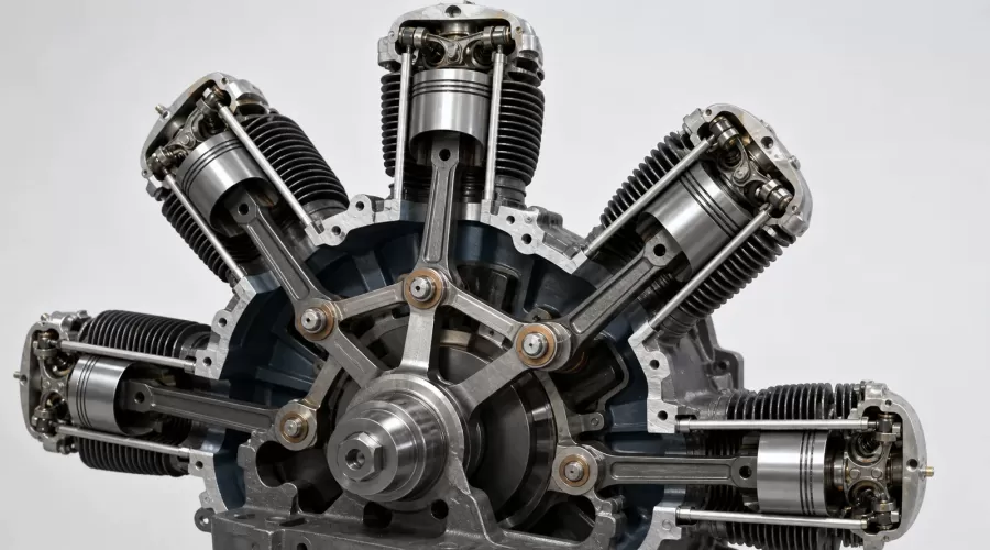
A radial engine master rod solves a packaging problem: several pistons arranged around one crankcase must transfer force to a single crankpin. One piston connects to a large master connecting rod whose big end runs on the crankpin. The other pistons connect through shorter articulating rods—also called link rods—that pivot on knuckle pins arranged around the master rod's big end.
The arrangement is compact, but the rods do not all share identical geometry. The crankpin center follows a circle around the crankshaft axis, while each knuckle pin follows a different path as the master rod swings. That is why a serious explanation must distinguish the master rod, articulating rods, knuckle pins, bushings and crankpin rather than calling every member simply a “connecting rod.”
Key takeaways
- The master rod alone carries the main crankpin bearing; the other rods pivot from the master rod.
- A knuckle pin is not the crankpin. It connects an articulating rod to the master-rod assembly.
- The master rod and link rods transmit alternating gas and inertia forces through different paths.
- Link-rod motion is not a perfect copy of the master rod's motion because each knuckle pin moves with the master rod.
- A visible model can teach the linkage even when an electric motor—not combustion—provides the motion.
- Exact clearances, fastener torques, lubricant and service limits are product-specific and cannot be inferred from a full-size aircraft manual.
The vocabulary: five parts that are easy to confuse
| Part | Where it pivots | Primary job | What to look for in a model |
|---|---|---|---|
| Crankshaft | Main bearings in the crankcase | Receives torque and carries the crankpin off its centerline | Smooth rotation, visible throw and no housing contact |
| Crankpin | Travels around the crankshaft axis | Supports the master rod's big-end bearing | One shared journal or a mechanism representing it |
| Master rod | Big end on the crankpin; small end at one piston | Connects one piston directly and supports the link-rod pivots | Enlarged big end or hub with several attachment points |
| Articulating/link rod | Knuckle pin at inner end; piston pin at outer end | Transfers force between another piston and the master rod | Separate inner pivots around the master hub |
| Knuckle pin and bushing | Mounted in or through the master-rod hub | Forms the articulating rod's inner bearing joint | Aligned, retained pivots without visible binding |
The Federal Aviation Administration's Powerplant handbook, Chapter 1, describes this as a master-and-articulated connecting-rod assembly. It explains that the master rod contains the crankpin bearing, while articulating rods attach to knuckle pins in the master rod. The terminology matters because each joint has a different motion and load path.
Why a radial engine needs a master-rod architecture
In a conventional in-line engine, each cylinder can often have its own crankpin or share a crankpin with a cylinder placed in a compatible plane. A single-row radial engine is different: its cylinders point outward around one crankcase, and their piston axes converge toward the crankshaft area. Giving every rod a full-width bearing on the same short crankpin would create an axial stacking problem and move rods out of their cylinder planes.
The master-rod assembly puts one large bearing around the crankpin and provides a ring of secondary pivots for the remaining rods. A 1929 Wright Aeronautical master-rod patent describes the basic engineering problem as connecting several pistons in separate radial cylinders to a common connecting-rod bearing so their forces reach the crankpin. A patent is not proof that every later engine uses the same details, but it is useful primary evidence of the design problem and one historical solution.
This architecture can be understood with three questions:
- Where does this rod pivot? The master rod pivots on the crankpin; a link rod pivots on a knuckle pin.
- What path does that pivot follow? The crankpin follows a circle; a knuckle pin is carried by the swinging master rod and follows a compound path.
- Where does the force go? A master-piston force goes through the master rod to the crankpin. A link-piston force first enters the master hub through a knuckle pin, then reaches the crankpin bearing.
How the motion actually travels
Start with one cylinder—the cylinder connected to the master rod. As its piston moves along the cylinder axis, the master rod's small end follows the piston pin. The big end turns around the crankpin bearing while the crankpin orbits the crankshaft axis. This is the familiar slider-crank relationship, complicated by the fact that the master hub also carries the other rods.
Now follow an articulating rod. Its outer end follows another piston pin, but its inner end is not centered on the crankpin. It pivots on a knuckle pin located some distance away from the center of the master-rod bearing. When the master rod swings, that knuckle pin changes position relative to both the crankshaft and its cylinder. The FAA handbook notes that knuckle-pin centers trace elliptical paths rather than the crankpin's circular path.
This does not justify a universal claim that every linked piston has a specific amount of unequal stroke. The actual displacement relationship depends on cylinder angle, master-rod length, link-rod length, knuckle-pin radius and angular location. Historical NACA/NASA archival analysis treats articulated-rod geometry explicitly when calculating radial-engine motion and forces. The safe conclusion is narrower: the link-rod kinematics differ from the master rod's simple reference geometry, so designers must calculate rather than assume identical paths.
How force moves through the assembly
During a combustion power event, cylinder pressure acts on the piston crown. The piston pin transfers that load into its connecting rod. In the master cylinder, the load passes through the master rod to the crankpin bearing. In a linked cylinder, it passes through the articulating rod, its inner bushing and knuckle pin, into the master-rod hub, and then to the crankpin bearing.
Loads are not one-directional. As the crankshaft accelerates and decelerates piston assemblies through each revolution, inertia forces reverse. Bending, bearing pressure and stress concentration can occur around the master hub and its pin holes. The IJERT master-rod analysis is a supplemental example of engineers evaluating stress and deformation under static and dynamic assumptions. It does not provide a permissible limit for an EnginesDIY product; only the manufacturer of a specific product can do that.
The U.S. War Department's historical technical manual independently describes articulated rods, knuckle pins and bearing arrangements. Together with the FAA material, it supports a practical observation: alignment and joint freedom matter because load must cross several interfaces before reaching the crankshaft.
Why bushings and pin retention matter
A pivot that carries alternating load needs a controlled bearing surface. Full-size master-and-articulated assemblies commonly use bushings at articulating-rod joints; the FAA describes bronze bushings in the link rods and knuckle-pin holes for the assemblies it covers. That is a design example, not a promise that every miniature kit uses bronze.
For a model, the important questions are observable:
- Does every link rod stay in its intended plane through a full hand-turned cycle?
- Do the knuckle pins remain fully retained?
- Is there visible rubbing between a rod and the crankcase, adjacent rod or cylinder skirt?
- Does one joint tighten at a repeatable crank angle?
- Does the supplied manual identify lubrication points and a compatible lubricant?
Do not “fix” a tight joint by randomly enlarging a hole, adding an unspecified lubricant or loosening a fastener. Each action changes alignment, clearance or retention. Stop and compare the assembly with the product manual or contact the seller/manufacturer with clear photographs.
One row versus several rows
A single-row radial needs one connecting-rod system for that row. In a multi-row radial, each cylinder row normally has its own crank throw and rod assembly. The FAA gives a useful counting example: an 18-cylinder, two-row engine has two master rods—one for each row—and 16 articulating rods.
This is why “one engine has one master rod” is not a safe general rule. The correct rule is closer to one master-and-articulated assembly per applicable cylinder row/crank throw. Exact arrangements can differ, and some unconventional engines use other mechanisms.
The Smithsonian's Kinner R-540 five-cylinder cutaway is a useful physical reference for a single-row radial layout. Museum cutaways help verify real component relationships, but they do not tell you whether a miniature display kit duplicates every internal bearing, oil passage or material.
What a radial engine model can—and cannot—prove
A good visible mechanism can make the master-rod concept easier to understand than an exterior photograph. In the radial engine model kits category, however, products may represent very different operating classes:
- Static or cutaway model: best for identifying parts and tracing a motion path slowly.
- Hand-cranked model: lets you feel binding and observe geometry without powered rotation.
- Electric-motor-driven model: repeats motion consistently but does not prove combustion, compression or power output.
- Fuel-burning model engine: adds combustion, ignition, cooling and lubrication requirements; it demands product-specific operating instructions.
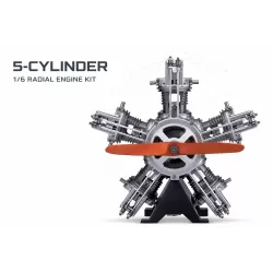
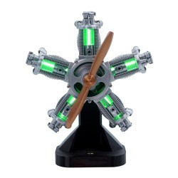
The ENJOMOR five-cylinder radial model kit and TECHING 1:6 five-cylinder radial model kit are relevant places to compare visible mechanism and assembly information. The NGH GF150R5 five-cylinder radial engine belongs to a different operating class. Do not transfer a display model's expectations to a fuel-burning engine—or vice versa—without reading the exact product page and manual.
For a broader decision framework, use our guide to working, motorized and cutaway model engine kits.
A practical inspection workflow for model builders
This workflow is deliberately non-destructive. It is suitable for a new unpowered assembly or a model whose manual permits hand rotation. It is not an overhaul procedure.
- Identify the operating class. Confirm whether the model is static, hand-cranked, motorized or fuel-burning. Find the supplied manual before moving anything.
- Find the master hub. Look for the large rod end around the crankpin and identify the one rod that continues directly to a piston.
- Count link rods and knuckle pins. In a five-cylinder single-row master-rod layout, you would ordinarily expect one master rod and four link rods. Treat product documentation as final.
- Check rod planes. Each rod should remain aligned with its piston and intended pivot. Photograph any spacer, washer or bushing position before assembly.
- Turn slowly. If permitted, rotate by hand through two crankshaft revolutions. Stop at resistance; do not use the motor to force a tight mechanism.
- Observe each inner joint. Watch whether every link rod changes angle freely around its knuckle pin without contacting a neighbor.
- Check retention. Verify that visible clips, screws, nuts or retainers match the instructions. Do not invent a torque value.
- Lubricate only as specified. Material compatibility and oil path vary. More lubricant is not automatically better.
- Run a low-energy check. If the product is motorized and the manual permits it, start at the lowest specified setting while observing alignment and sound.
- Document anomalies. A repeatable tight spot, fresh metal dust, pin migration or rod contact is evidence to stop and seek support.
How this linkage relates to the four-stroke cycle
The rod assembly converts reciprocating piston motion into crankshaft rotation; it does not determine the combustion sequence by itself. Valve timing and ignition coordinate the cycle. Our guide to how a miniature four-stroke engine works explains intake, compression, power and exhaust. The separate valve timing and valve lash guide covers how cam and valve events relate to crank position.
In a conventional four-stroke single-row radial, firing order is also linked to the odd-number-per-row pattern. That question is treated in depth in why radial engines use odd cylinder counts. Keeping the topics separate prevents a common mistake: using firing order to explain a mechanical bind that actually originates in rod alignment or joint geometry.
Selection framework: choose the evidence you want to observe
| Your question | Most useful model feature | Evidence you should request | What not to assume |
|---|---|---|---|
| How do several pistons share one crankpin? | Open crankcase or transparent cutaway | Clear photos of master hub, link rods and pins | Exterior cylinder count proves internal detail |
| Do all joints move freely? | Hand rotation before powered operation | Assembly manual and full-cycle video | A motor can safely overcome resistance |
| Does it reproduce combustion? | Documented fuel-burning operating system | Fuel, ignition, cooling and starting specifications | Moving pistons mean the cylinders fire |
| Is it suitable for teaching? | Visible parts, controlled speed and clear instructions | Accurate terminology and supported age/supervision guidance | More parts automatically mean better learning |
| Can it be maintained? | Accessible joints and available spares | Manufacturer service procedure and parts list | Aircraft-engine limits apply to a model |
Limitations and safety
This article cannot identify the internal design of a product from an exterior image alone. A model may simplify, conceal or replace the full-size master-rod mechanism. Product photographs can also show a pre-production configuration. Verify the current manual, included parts and operating method before purchase or assembly.
Never rotate a fuel-burning engine with ignition enabled unless its manual explicitly requires a controlled procedure and you understand the risks. Keep propellers, flywheels, belts and exposed linkages clear of hands, hair, clothing and tools. A bind, loose pin or unexpected noise is a stop condition—not a reason to add speed. For a new fuel-burning model, follow the product-specific procedure and the general cautions in our miniature four-stroke break-in guide.
Frequently asked questions
Does every radial engine have one master rod?
No. A conventional single-row radial commonly uses one master-and-articulated assembly for that row, while a multi-row engine can use one assembly per row/crank throw. Unconventional designs may use other connecting mechanisms.
Is an articulating rod the same as a connecting rod?
It is a type of connecting rod. In this architecture, “articulating” or “link” distinguishes the rods whose inner ends pivot on knuckle pins in the master rod from the master rod that carries the main crankpin bearing.
Why are the link rods attached around the master rod?
The arrangement allows several radial pistons to transfer force toward one crankpin without stacking a full-width crankpin bearing for every rod. It keeps the rods closer to their cylinder planes and creates a compact shared assembly.
Do all radial-engine pistons have exactly the same motion?
Do not assume that from appearance alone. A master rod pivots on the crankpin, while a link rod pivots on a knuckle pin carried by the master hub. The resulting geometry must be calculated from the actual dimensions and pin positions.
Can I diagnose a tight model by running it faster?
No. Increased speed can turn misalignment or poor retention into damage. If the manual permits hand rotation, stop at the repeatable tight point, inspect rod planes and pin retention, and obtain product-specific support.
Does a motorized radial model use real combustion?
Not necessarily. An electric motor can drive realistic piston and rod motion without compression, ignition or combustion. Confirm the energy source and operating description for the exact product.
Conclusion
The useful way to read a radial engine mechanism is not simply to count cylinders. Find the crankpin, identify the master rod, trace each articulating rod to its knuckle pin, and follow the force path back to the master bearing. Then ask whether the model is a cutaway, a motorized demonstration or a live engine. That sequence turns an impressive-looking mechanism into something you can explain, inspect and select with evidence.
References
- U.S. Federal Aviation Administration, Aviation Maintenance Technician Handbook—Powerplant, Chapter 1.
- U.S. War Department, technical manual section on radial-engine connecting rods, hosted by GovInfo.
- Smithsonian National Air and Space Museum, Kinner R-540 Radial 5 Engine Cutaway.
- National Advisory Committee for Aeronautics, historical radial-engine connecting-rod analysis, NASA Technical Reports Server.
- Edward T. Jones / Wright Aeronautical Corporation, U.S. Patent 1,723,175: Master Connecting Rod for Radial-Cylinder Engines.
- Static and Dynamic Analysis of Radial Engine Master Rod Using ANSYS, IJERT.
Related Products
Leave a comment