

Quick Answer
A Stirling engine generator can show a voltage and still lack the usable power to run your chosen device. An unloaded voltmeter reading does not establish output current, stable loaded voltage, continuous watts, regulation or device compatibility. To evaluate a model, identify its generator and approved load, document a repeatable unloaded baseline, and compare it with a manufacturer-approved loaded measurement under the same operating conditions. Do not use a phone, battery, short circuit or arbitrary low-resistance load as a test. If the engine slows sharply, stops, overheats or becomes unstable, remove the approved load safely and end the run according to the manual.
The V-L-R evidence ladder separates voltage, load and repeatability. It is an editorial recording framework: first ask what voltage was measured, next ask what load was connected, then ask whether the result was stable and repeatable. It is not a certification method, a new product rating or permission to exceed operating limits.
Key takeaways
- State whether a reading is unloaded or loaded. A number without operating conditions is weak evidence.
- Separate mechanical running, generation, regulation and useful device operation. Success at one stage does not prove the next.
- Use only an approved measurement connection and load. Do not discover a rating by repeatedly forcing the model to stall.
- Record warm-up conditions, measurement location, load identity and duration. A short video of a bright LED is not a continuous-power specification.
- Choose a model around the experiment you want to explain, not an unsupported charging or household-power expectation.
Follow the energy chain before changing anything
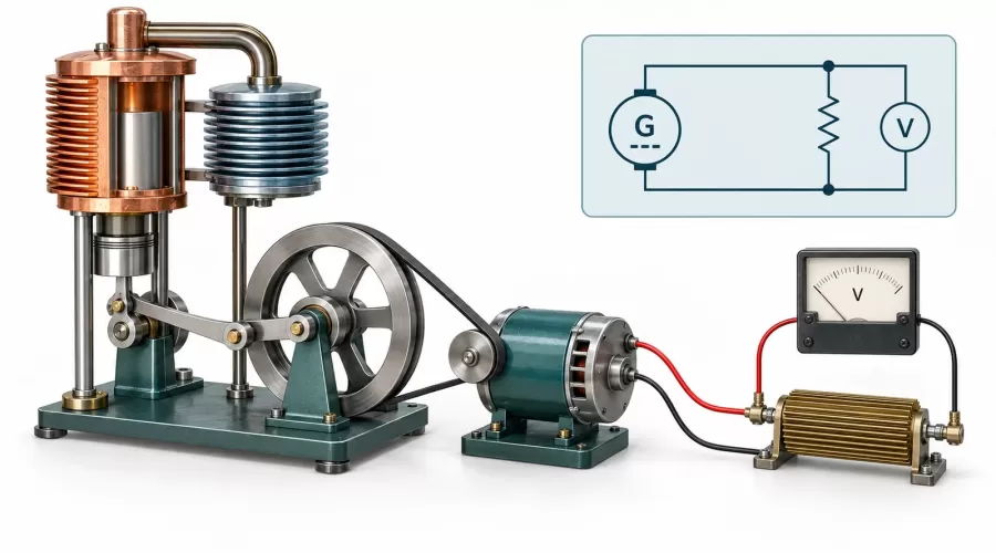
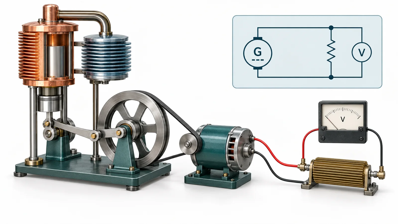
For a heat-driven generating model, the relevant chain is heat transfer, engine motion, mechanical transmission, generator output, and electrical load. A problem at any interface can appear as an electrical symptom. Start by drawing those five boxes for your exact model. Mark which components are supplied, which are optional, and which are integrated into an assembly that must not be opened. This often reveals that two apparently similar kits are intended for different demonstrations.
The U.S. Department of Energy's dish/engine explanation describes heat being converted into mechanical work that drives a generator. That is useful background for the energy chain, not a basis for assigning a small tabletop model the output of a solar installation. Keep system scale and design context explicit.
If a model fails to run even with its normal demonstration load disconnected in the way the manual permits, solve the mechanical problem first. Our Stirling engine troubleshooting guide discusses heat, friction, leakage and phase. The regenerator and phase-angle guide explains the thermal mechanism. This article begins where a mechanically running engine meets an electrical load; it does not replace either guide.
NASA's dynamic thermal energy conversion overview illustrates another boundary: engineered Stirling convertors use dedicated alternators, controllers and test programs. A free-piston space-power convertor is not the same architecture as a flywheel-driven educational model with a small rotary generator. Do not transfer research-system efficiency or longevity claims to a kit.
Why the flywheel may slow when a load is connected
For a brushed permanent-magnet DC motor used as a generator, maxon's generator guidance relates induced voltage to rotational speed and explains the terminal-voltage loss associated with winding resistance and load current. Electrical loading also requires driving torque. If the engine cannot sustain the added demand, its speed may fall, affecting the available output. These principles apply only after you identify the generator type; brushless or electronically conditioned outputs require their own documentation.
A larger flame is not a diagnostic answer. Nor is tightening a belt, moving a pulley or changing a linkage without a manual. Those changes introduce new variables and may exceed thermal or mechanical limits. Your first useful question is simpler: did the behavior change when the approved load changed, while the rest of the documented setup stayed the same?
Volts are not watts: read the complete claim
A voltage display can be an excellent teaching feature, but it tells you only one part of the story. To evaluate a claim such as “produces electricity,” ask whether it means visible LED operation, a measurable unloaded voltage, a specified load being supplied, or a regulated output suitable for a particular device. These are different claims and need different evidence.
OpenStax's electrical power chapter gives P = V × I for DC power, with voltage in volts, current in amperes and power in watts. For a known ohmic resistor, the corresponding relation is P = V² / R. Use the voltage measured across that same resistor while it is connected, not an earlier unloaded value. These simple expressions do not make an unknown electronic load equivalent to a resistor.
Hypothetical arithmetic, not a model test: suppose an approved 100-ohm resistor has a steady 2.0 V across it. Its dissipation is 2.0²/100 = 0.040 W, or 40 mW. A separate unloaded 5 V reading would not justify claiming 0.25 W into that resistor: the connected voltage was 2 V. Neither number demonstrates phone charging, overall thermal efficiency or the maximum safe output of a real engine. No EnginesDIY product was bench-tested to create this example.
Also identify the measurement boundary. Power at raw generator terminals is not automatically power delivered after a rectifier, regulator, indicator board or cable. A built-in LED or display may already be a load. Therefore “no external load” can be a more honest description than “open circuit” when the integrated circuitry remains connected.
Why a boost converter is not extra energy
A step-up board can change voltage; it does not create additional input power. Texas Instruments' Working with Boost Converters uses input/output power balance to explain the associated current demand and conversion losses. Startup behavior and input limits must also be checked for the actual circuit. Adding a converter to a weak or unstable source may therefore fail to solve the underlying mismatch.
Do not buy a board merely because its advertised output voltage resembles a phone charger. Without verified source capability, regulation, protection and device compatibility, the combination is an unfinished engineering project. For a learning demonstration, a supplied indicator and an honest measurement log are usually a clearer objective than connecting valuable electronics.
The V-L-R measurement workflow
Use this workflow only for an isolated, low-voltage educational model whose manual permits the proposed measurement. Unknown output, exposed mains wiring, damaged insulation, pressurized modifications or missing operating instructions are reasons to stop and obtain qualified help. You do not need a complete load curve to answer a modest question such as whether a specified demonstration load operates consistently.
V: document the voltage baseline
- Identify the model. Record its manual revision, generator type, approved heat source, normal demonstration accessories and stated operating limits. Photograph the cold setup before running, without including personal information.
- Choose the measurement point. Use the terminals or test points named by the manufacturer. State whether you are measuring raw generator output or conditioned output.
- Prepare while stopped and cool. Check meter ratings, lead condition, input sockets and the correct voltage mode. Secure permitted connections away from the flywheel, belt and hot chamber before starting.
- Use the normal operating procedure. Follow the manual's warm-up and cooling instructions. Do not invent a universal burner setting or temperature target from a different model.
- Record a bounded observation. Note the time after startup, voltage range and visible running behavior. Describe “no external load” accurately if built-in accessories remain active.
Fluke's DC voltage measurement guide supports choosing the appropriate function and connecting voltage probes across the measurement points. Consult your own meter manual as well. Never leave a lead in a current-input socket and treat it as a voltage connection; a mistaken connection can create a short circuit. This article does not provide a universal series-current wiring procedure.
L: compare one approved loaded condition
Switch loads only as the exact model instructions allow. Some setups require shutting down, cooling and reconnecting before another run. Do not hold bare wires against terminals, reach over moving parts, bypass a built-in control or substitute a short circuit. If the manufacturer does not identify an acceptable test load or measurement procedure, stop at the baseline and ask for documentation.
For an approved resistive demonstration load, record its resistance, power rating and connection location, then measure the connected voltage. For a supplied LED assembly, record the exact assembly rather than guessing its resistance from brightness. If current cannot be measured safely with the documented arrangement, enter “not measured.” Unknown current is better evidence than an invented wattage.
R: check repeatability, not endurance limits
Repeat only within the manual's duty cycle. Use the same approved setup, measurement boundary and observation window, with the required cooling interval. Compare ranges rather than cherry-picking the highest instantaneous number. If the later run differs, inspect your record for changes in warm-up, ambient conditions, accessories, connection position or measurement timing before blaming the generator.
Report what you actually observed: for example, “supplied LED remained lit during the documented observation window,” not “continuous power source.” Record a stopped run and its reason as carefully as a successful run. Never keep a stalling or overheating model operating just to obtain a longer video.
| Field | Baseline | Approved load | Repeat |
|---|---|---|---|
| Manual, setup and heat source | Record | Record any change | Match setup |
| Measurement point and output type | Record | Same boundary | Same boundary |
| Time after startup / observation window | Record | Record | Record |
| External and integrated loads | Identify both | Exact load identity | Same load |
| Voltage range / current | Measure / not measured | Measure / not measured | Measure / not measured |
| Power calculation validity | Not a loaded rating | State method or unknown | Compare like with like |
| Speed behavior / shutdown reason | Record | Record | Record |
If speed is relevant and the model permits non-contact observation, our optical tachometer guide explains common false readings. Never add reflective material or move a sensor near a running mechanism. An unverified RPM reading should not become a confident explanation for an electrical result.
Interpret symptoms without guessing
| Observation | First evidence to check | Avoid |
|---|---|---|
| Runs poorly before adding an external load | Normal mechanical setup and manual procedure | Starting with an electrical redesign |
| Runs normally, but no credible voltage reading | Output type, approved test point, meter mode and lead placement while stopped | Assuming every generator output is DC |
| Stops when the approved load is added | Load identity, permitted connection and change from baseline | More heat, repeated forced stalls or short-circuit tests |
| Indicator flashes or electronics reset | Exact accessory compatibility and measured behavior | Calling a peak reading a stable supply |
| Works once but not in the repeat run | Observation timing, setup changes and duty-cycle compliance | Comparing unmatched runs |
Send support a compact evidence package: exact model, manual revision, cold setup photograph, accessory identity, measurement boundary, baseline and loaded observations, and the stop reason. Describe uncertainty. “Display changed while the flywheel slowed” is more useful than “the generator is defective,” because it preserves the observation without prematurely assigning the cause.
Choose the right learning model and ask for the right evidence
Begin with the learning question. If you want to see how external heat produces motion, browse Stirling engine kits and compare the visible mechanism, documentation and supervision requirements. If you want to connect motion to an electrical indicator, the Stirling generator model category is the relevant starting point. A mechanism display and a rated power supply should not be treated as interchangeable purchases.
The ENJOMOR diamond-linkage generator with voltmeter provides a product-specific place to inspect the stated demonstration features. The hot-air generator with colorful LED illustrates a different indicator-centered presentation. These links are comparison starting points, not endorsements of an unverified wattage or phone-charging capability. Confirm the included components and current manual before choosing.
- Ask what is measured. Is an advertised voltage open-terminal, under a named load, or a built-in display reading?
- Ask what is included. Is the generator, indicator, wiring, controller and suitable operating documentation supplied?
- Ask what is supported. Which external loads and measurements does the manufacturer explicitly permit?
- Ask what the duty cycle means. What warm-up, supervision, shutdown and cooling procedure applies?
- Ask for bounded evidence. A loaded output specification should state conditions, duration and measurement location, not just an attractive peak number.
If you want motion without managing a heat source, revisit our working versus motorized model comparison. That may be the better fit for a desk display or an assembly-focused lesson. Making the intended experiment explicit can prevent both a disappointing purchase and an unsafe attempt to extract unsupported performance.
Safety and limitations
Hot surfaces, approved fuel or heat sources, moving linkages and electrical connections require competent adult supervision. Use the specified stable surface, ventilation and clearance. Keep wires, hair, clothing and test equipment clear of moving and heated parts. Refill, reconnect or service only according to the exact shutdown and cooling instructions. Do not operate a damaged model or improvise a pressure-system modification.
This guide is limited to documented low-voltage educational setups. It does not cover mains generation, grid connection, household backup power, battery charging, USB compliance testing, efficiency certification or maximum-power extraction. A terminal voltage reading cannot establish those capabilities. Do not connect a phone, power bank, battery, home wiring or valuable electronics unless the manufacturer explicitly supplies and supports that complete application.
The framework combines primary-source principles with original editorial decision aids; it contains no proprietary model measurements. Component tolerances, generator architecture, rectification, integrated loads, measurement bandwidth and changing operating conditions can affect interpretation. If you cannot identify the output type, safe connection or approved load, stop rather than guessing.
Frequently Asked Questions
Why does my Stirling generator show voltage but not run a device?
The voltage reading does not establish the complete loaded operating condition. Check the exact supported accessory and documentation. Record the measurement point, load identity and running behavior instead of treating one unloaded number as a device-compatibility guarantee.
Does lighting an LED prove the generator can charge a phone?
No. The supplied indicator demonstrates its own operation under the observed conditions. Phone charging requires a supported complete output system, not just an LED or a USB-shaped connector. Keep unsupported valuable devices disconnected.
Should I test the maximum output by shorting the terminals?
No. A short circuit is not an approved demonstration load and may damage components or stall the engine. Use only the manufacturer-approved measurement method and load, or ask support for the missing information.
Can I calculate watts from a built-in voltage display alone?
No. You need a valid loaded measurement method. For an approved known ohmic resistor, use its actual connected voltage and resistance; for an unknown electronic accessory, report current or power as unknown rather than inferring it from brightness.
Will a boost converter fix a weak generator?
Not necessarily. It adds an electrical conversion stage with its own requirements and losses. Evaluate the entire documented system first. A board's voltage setting is not evidence that the source can supply the intended application.
Why should I repeat a successful demonstration?
A matched repeat helps distinguish a dependable observation from a brief favorable moment. Repeat only within the permitted duty cycle and cooling requirements. Record changing conditions, voltage ranges and stop reasons; do not perform an endurance test.
What information should I request before buying?
Request the exact manual, included generator and accessories, supported loads, operating limits, and conditions behind any loaded output claim. If the goal is mechanism learning rather than useful power, choose and evaluate the model on that basis.
Conclusion
A good Stirling generator demonstration makes an energy conversion visible and explainable. Its value does not depend on an exaggerated wattage or charging promise. Use the V-L-R ladder to state the voltage boundary, identify the approved load, and check repeatability within the manual. Then choose a model and lesson around the evidence you can genuinely obtain.
References and evidence method
Reviewed September 17, 2026. These independent primary sources support the identified general principles, not the output rating of any listed kit. The measurement log, symptom triage and purchasing checklist are original editorial synthesis. No hands-on product testing is claimed.
- maxon: Motors as Generators — rotary motor-generator relationships and architecture boundaries.
- OpenStax: Electrical Energy and Power — DC power and ohmic-resistor equations.
- Fluke: How to Measure DC Voltage — voltage-measurement function and connection principles.
- Texas Instruments: Working with Boost Converters — power balance and converter limitations.
- U.S. DOE: Dish/Engine System Basics — thermal-to-mechanical-to-electrical conversion chain.
- NASA Glenn: Dynamic Thermal Energy Conversion — engineered Stirling convertor context and limits of comparison.
Leave a comment