

By EnginesDIY Editorial Team | Published and reviewed September 25, 2026
Quick Answer
Use the retainer specified for the exact piston, pin and engine revision. A piston-pin circlip or other lock prevents a floating wrist pin from moving far enough to contact the cylinder wall. Before assembly, identify the retention architecture, inspect both pin-boss grooves, select the specified new clips and follow the maker's installation order and orientation. After fitting each clip, verify that it is fully seated around its intended groove and that the pin has only the movement the manufacturer permits. If the groove, clip shape or manual is uncertain, stop before closing the cylinder. A clip that merely looks close is not an accepted installation.
The I-S-M record checks clip identity, full groove seating and pin movement before the cylinder is closed. This is a workshop documentation aid, not a replacement for a service manual or a claim that an engine has passed a running test. “Identity” records the piston, pin and retainer part numbers; “seating” records a visual and tactile check of the entire groove circumference; “movement” records the maker-specified pin behavior and any unexplained drag or axial travel. Do not turn a generic article into a clearance specification.
Key takeaways
- A free-floating pin usually needs positive axial retention; a fixed or press-fit pin may use a different design. First identify which assembly is actually on the bench.
- Wire clips, stamped snap rings and spiral locks are not synonyms. The groove and pin-end geometry belong to the named design, not to a generic clip diameter.
- A clean, undamaged groove matters as much as the new retainer. A clip perched on the entry chamfer can masquerade as installed.
- Do not reuse a clip that has been expanded, nicked, stretched or removed unless the exact maker explicitly permits it. Replacement is normally the conservative choice.
- Shield the crankcase opening, work over a contained bench and use eye protection: a small retainer can launch, disappear into an engine or scratch a pin bore.
- Do not run an engine with a missing, uncertain or visibly unseated clip. The damage mechanism can include pin migration and cylinder-wall scoring.
What does the retaining clip actually do?
The wrist pin joins a piston to the connecting rod's small end. Depending on the design, the pin may rotate or slide relative to the piston and rod, or it may be fixed to one member. Where the pin is free to move sideways, retainers at the piston bosses keep it from walking toward the cylinder wall. MAHLE's circlip note distinguishes floating pins from fixed-pin rods and explains why clip tension after removal is a concern. That is a mechanical principle, not permission to copy an automotive clip's size into a model engine.
Small engines differ visibly. Some use open wire retainers, some use stamped rings, and some use a proprietary retainer supplied as part of a piston/rod set. JE Pistons describes multiple wrist-pin lock families and the different groove and pin features they need. A similar-looking ring can have the wrong wire section or free diameter. Do not select it because it snaps into the hole or because a seller lists the same nominal piston diameter.
The O.S. SPEED T1203 model-engine manual lists a piston pin, a specific retainer and a dedicated retainer tool. It illustrates the correct sourcing logic: model and revision first, exploded part number second, supplier substitution only with an explicit approved cross-reference. It does not show that those parts fit another O.S. engine, let alone every small combustion engine.
Work out whether a new piston kit includes its own retainers. If it does, keep the clip, pin and piston as one documented set until the maker permits a different combination. A ring that fits the groove but interferes with the pin-end chamfer can be as unsafe as a loose ring. The piston-ring end-gap guide addresses a different part of the top end: it cannot confirm that a wrist-pin retainer has seated.
The I-S-M bench workflow
1. Isolate the engine and preserve the as-found state
Stop the machine, cool it and disable ignition, starter power and fuel according to its own manual. Remove a plug lead or battery only by the maker's method; a hot cylinder, sharp propeller or unexpectedly energized starter is a poor place to discover that the engine could still turn. If it is an aircraft or vehicle engine, follow its dedicated service requirements. Photograph the piston crown, rod orientation, pin bosses and both old clips before disassembly. Bag parts by side and part number instead of pooling visually similar rings.
Cover the crankcase opening with a clean, removable barrier so a clip cannot fall inside. Keep fibers, tape adhesive and loose paper out of oilways and bearings. Set a bright lamp and a raised-edge work mat. Wear eye protection and use a suitable tool with controlled tip geometry. Our model-engine kit tools and assembly checklist explains why compartment trays and correct-size tools are valuable in a miniature build. If the original clip is already missing, do not assume it left the engine: find it before closing the case.
2. Verify identity before using force
Record the exact engine model, revision, piston and pin part numbers, retainer part number and manual edition. Compare the old retainer with the specified new component only as an inspection aid; damage can change its free shape. Check whether the maker wants one clip installed before the pin, and from which side the pin must enter. The ProX top-end procedure explicitly treats the service manual as the authority for clip orientation. Its procedure is a useful example, not a universal model-engine sequence.
Do not mix a retainer from a full-size piston with a small model-engine groove, even if a catalog measurement appears close. CP-Carrillo's wire-lock instructions describe a named lock and its seating check. They reinforce the need to match parts and installation directions, but their automotive tools and contact-force procedure do not transfer by scale. When the miniature-engine instructions are unavailable, leave it unassembled and obtain them.
3. Inspect the groove, boss and pin
With the piston supported, inspect the machined groove on both sides under light and magnification. Look for burrs, displaced metal, embedded grit, corrosion and asymmetry. A groove can be present yet too damaged to retain the intended ring. Check the bore entry and the pin end for a raised edge or scratch that might make a correct clip appear seated while it is riding on the chamfer. A clip with a flattened tip, expanded opening, unknown history or visible distortion should not be reused as a diagnostic shortcut.
Do not file or deepen a groove to fit a substitute part. That changes the piston boss, a highly stressed feature, without a manufacturer design check. Do not polish away unexplained scoring simply to make the new pin pass through. If you see damage on the piston skirt or bore, the separate compression-test guide can frame later functional diagnosis, but compression alone cannot establish whether a retainer is intact. First resolve the mechanical retention fault.
4. Install each clip by the exact maker method
Follow the model's specified orientation, approved tool and assembly order. Some open rings have an orientation relative to piston travel, while some designs require different treatment or have a notch in the boss. MAHLE describes orientation for a particular open-ring case; never transfer that sentence to a wire lock or proprietary retainer without confirmation. Bring a clip into its groove using controlled pressure. Avoid overexpansion, twisting, scratching the bore and levering against a thin boss wall. The clip should settle into the intended groove, not into a nearby chamfer or casting mark.
Install the first side only after confirming that the pin can still be inserted in the prescribed direction. Support the piston and connecting rod during pin insertion so a tight fit is not mistaken for a license to hammer through an unsupported small-end bearing. Use the lubricant and pin-fit procedure specified by the engine maker. Our lubrication guide explains why a glow engine, gasoline two-stroke and four-stroke may deliver oil differently; it does not choose a pin assembly oil for a named engine. Complete the opposite clip only when the first-side condition is established.
5. Inspect full seating and movement before closure
Inspect the entire circumference, not just the visible end tips. The ring should be visibly inside its intended groove all the way around, with no section perched on the entry edge. Check by the precise visual or non-marring probe method allowed by the manufacturer. ProX warns that a retainer that rotates or is deformed after installation can be compromised in its example procedure. Treat any unexpected rotation or loose feel as a stop signal to consult the exact manual, rather than applying a blanket rule to every retainer design.
Check the wrist pin's axial relationship and free movement only within the maker's prescribed test method. A pin that presses abnormally hard against one clip, binds in the small-end bearing or seems to move farther than the drawing allows needs investigation. Do not publish a millimeter clearance from a generic article. Take a dated close-up photo of both installed clips and record the verified part numbers, groove condition and permitted movement. The I-S-M record is complete only when each of those three categories has evidence, not a tick based on memory.
6. Reassemble and stop on anomalies
Remove the crankcase barrier deliberately and account for every clip and tool. Confirm piston direction, rod orientation, ring position and cylinder fit in the model's own assembly order. Never force the cylinder over a ring, and never rotate the crank with unexplained resistance. The bearing clearance and endplay guide explains a different source of binding; a stiff crank after top-end work should not automatically be blamed on the new clip. Keep a clear before/after record so a qualified mechanic can isolate the last changed step.
Fault-to-evidence table
| Observation | Possible cause | Safe next evidence | Do not do |
|---|---|---|---|
| Clip appears high on one side | Section perched on chamfer, grit or wrong ring section | Stop; magnified full-circumference inspection against the specified drawing | Close the cylinder because the ends look seated |
| Clip launches or loses its shape | Tool slip, overexpansion, wrong installation path | Recover every fragment, inspect groove and use a specified new clip | Stretch it back and reuse it |
| Pin drags after second clip | Axial stack, burr, damaged small end or wrong pin/clip | Compare the maker's assembly sequence and permitted pin movement | Hammer the pin or run the engine to wear it in |
| Cylinder wall has a vertical score | Possible migrating pin or other hard debris; cause unproven | Inspect both retainers, pin ends and bore with engine isolated | Assume new rings alone repair the fault |
| Clip part number cannot be verified | Mixed kit or undocumented substitution | Find the exact exploded drawing and supplier confirmation | Choose by approximate diameter alone |
A mark, noise or score does not prove a single cause. Grit, ring failure, a broken bearing, improper lubrication and overheating can produce overlapping symptoms. The vibration diagnosis guide helps separate a top-end mechanical issue from propeller, mount and bearing problems after the engine is safely isolated. Record what is observed and what remains unknown.
Evidence limits, purchasing and safety
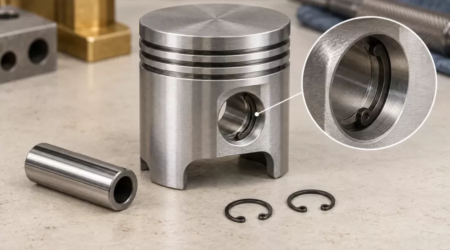
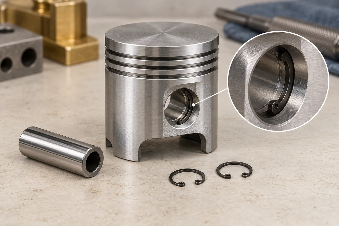
The five primary references below span automotive pistons, powersports top ends and an O.S. model engine. They agree on the central need for correct part identity and secure retention, but they do not establish one clip form, gap direction, insertion tool, torque or service interval for every miniature engine. This page contains no physical fit test and no verified compatibility list. The featured image is conceptual, and its proportions are not measurements. An EnginesDIY product page can help identify a kit family, but a photograph or category label is not a service manual.
When considering a model-engine kit, ask whether the supplier provides the exploded drawing, piston/pin/retainer part numbers, replacement clips and service instructions. Those facts are more useful than a generic “easy to assemble” claim. If the engine will fly, drive a vehicle or run near people, its manufacturer and appropriate qualified technician must set the acceptance criteria. Do not experiment with an uncertain retainer in an operating engine.
Keep fuel, flames and energized ignition away from the assembly bench. Cover springs and clips against flight, wear eye protection and contain removed components. Never mouth-blow, fuel-prime or start an engine to see whether a doubtful clip holds. A small clip can cause a large internal failure. If a groove is chipped, a boss cracked, a pin scored or a clip identity unresolved, replace or obtain maker-approved repair guidance before operation.
Frequently asked questions
Can I reuse a piston-pin circlip after removing it?
Normally treat a removed or distorted clip as a replacement item; MAHLE and JE describe retention or damage concerns. Follow the exact piston maker if it states a different service rule. Do not reuse one merely because it still springs outward.
Should the opening face up or down?
Some open-ring procedures specify a clock position, but the rule depends on the clip type and piston design. Use the exact manual and supplied retainer. Do not apply an automotive open-ring instruction to a different wire lock or miniature proprietary retainer.
How do I know the clip is fully seated?
Inspect the complete groove circumference under light and magnification, using the maker-approved non-damaging check. No segment should remain on the entry chamfer. If you cannot see or establish the condition, stop before installing the cylinder.
Is a clip that rotates in the groove always bad?
Unexpected movement is a warning, not a substitute for identifying the design. ProX rejects a freely rotating, deformed circlip in its example. Consult the exact model instructions to determine the permitted retention behavior; never declare an unknown clip acceptable from a casual spin test.
Can I buy a generic clip of the same diameter?
Diameter alone is insufficient. Cross-section, material, free shape, boss groove, pin-end geometry and installation method matter. Get an approved part number or written manufacturer equivalence before substituting.
What if I lost a clip into the crankcase?
Do not rotate or start the engine. Keep it isolated, retrieve and account for the clip using a maker-approved disassembly method, then inspect for scratches or fragments. Do not assume it will pass harmlessly through the engine.
Conclusion
The most reliable piston-pin retainer check is not “it snapped in.” It is a documented match between the named piston, pin, clip and groove; full circumferential seating; and the pin movement permitted by that engine's instructions. The I-S-M record makes those three facts explicit before a cylinder conceals them. If any one remains unknown, pause the assembly and obtain the model-specific evidence. That small delay is safer than treating a missing specification as permission to guess.
References and review limits
- MAHLE, Technical Messenger 12/2022: piston-pin circlips — retention architecture and type-specific installation.
- JE Pistons, Wrist Pin Locks — lock types, groove condition and seating.
- ProX Racing Parts, Two-Stroke Top-End Rebuild — manual-specific clip installation and inspection.
- CP-Carrillo, Wire Lock Installation — lock-specific engagement check that is not a miniature-engine specification.
- O.S. SPEED T1203 instruction manual — model-specific pin, retainer and tool example.
Reviewed by EnginesDIY Editorial Team on September 25, 2026. Search volume and PAA frequency for this specific topic are UNKNOWN. No cited source establishes a universal miniature-engine dimension or validates a particular EnginesDIY product's parts compatibility.
Leave a comment