

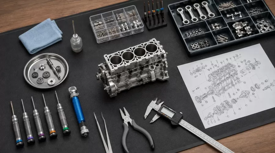
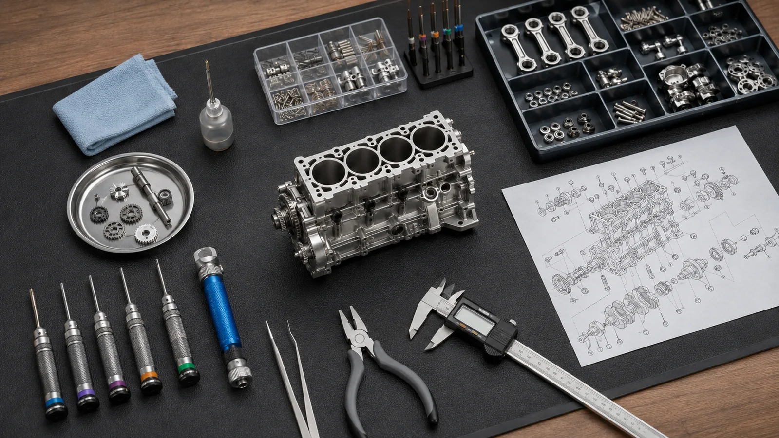
Metal model engine kits compress a real mechanical system into a small package. That makes them satisfying to build, but it also makes poor tool fit, contamination, and excessive force disproportionately damaging. The goal is not to assemble as fast as possible. The goal is to preserve thread form, bearing surfaces, timing relationships, and the ability to diagnose a problem later.
The safest build sequence is inventory, clean, measure, trial-fit, torque, rotate, and verify. This checklist controls the process; the kit maker's drawing and manual remain the authority for part orientation, lubricant, clearance, torque, timing, fuel, heat, and first-run limits.
1. Read the Kit Before Choosing Tools
First determine what kind of model is on the bench. A motorized display kit, an air-powered demonstrator, and a fuel-burning miniature engine can look similar in photographs but have very different commissioning requirements. If you are still comparing formats, start with our guide to working versus motorized model engine kits and the broader model engine kit collection.
Open the manual before opening every parts bag. Note the fastener drive types and sizes, any supplied jigs, the order of bearing and shaft installation, timing references, lubricant callouts, and operations that require threadlocker. Photograph each labeled bag and the tray layout. If the parts list has item numbers, preserve those numbers in your own trays. This creates a recoverable state if the build is interrupted.
Do not assume that a tool recommended for a full-size car engine is appropriate. Miniature kits often use small steel fasteners in aluminum or zinc-alloy components. The fastener may survive a torque that damages the female thread. That is why the manual's value, when provided, takes priority over generic charts.
2. Essential Model Engine Kit Tool Checklist
| Tool or supply | Purpose | Selection rule | Warning sign |
|---|---|---|---|
| Correct-size hex drivers and screwdrivers | Seat fully in miniature fasteners | Use the exact metric or imperial size; prefer crisp, unworn tips | Rocking, partial engagement, or visible rounding |
| Fine tweezers or hemostat | Handle clips, shims, springs, and washers | Use smooth jaws near finished surfaces | A part launches or must be forced into place |
| Compartment trays | Preserve the parts-list sequence | One subassembly or item group per compartment | Fasteners of similar length become mixed |
| Clean bench mat and lint-free cloth | Control contamination and protect finishes | Use a light or contrasting area for tiny parts | Visible grit, fibers, or metal chips |
| Digital or vernier caliper | Compare shafts, spacers, fastener lengths, and depths | Zero and clean the jaws before each measurement | Readings change with jaw pressure or angle |
| Small oil applicator | Place only the specified lubricant | Keep separate applicators for incompatible oils | Oil reaches threadlocker, belts, friction drives, or electrical parts |
| Magnification and directed light | Inspect burrs, thread starts, clips, and timing marks | Use shadow-free light from more than one angle | A component orientation cannot be confirmed visually |
The model-building tools and workshop equipment category is a convenient reference, but the kit manual should determine the final shopping list. If a powered driver is used, treat it as a low-speed run-down tool, not as the final authority. The last tightening step should be controlled and felt by hand unless the manual specifically approves a powered process.
3. Optional Precision Tools: When They Actually Help
A low-range torque screwdriver is useful when the manufacturer gives a torque specification that falls inside the tool's calibrated range. Cam-over designs disengage at the set value, helping reduce operator variation and over-tightening. Mountz explains this principle in its adjustable torque screwdriver guide, while Wera publishes the range and accuracy for one selectable torque screwdriver. These sources explain tool behavior, not a universal torque for your kit.
A pin vise, plastic or wood probe, soft-jaw pliers, feeler gauges, machinist's square, and small magnetic parts dish can also help. A micrometer may be appropriate when the manual specifies a fit that is too small for a general caliper to resolve. A dial indicator can expose shaft runout, but only if you understand the fixture and reference surface. Precision-looking numbers are not useful when the measurement method is unstable.
Before buying more equipment, inspect the kit-specific product page and manual. Some inline engine assembly kits include specialized fixtures or pre-machined relationships that eliminate operations expected in a full-scale engine build.
4. Build a Clean, Recoverable Workbench
SKF's bearing maintenance handbook recommends protecting bearings and mounting positions from dust, dirt, and moisture until installation. The same principle is valuable at model scale. A particle that looks trivial beside the engine can still mark a small journal or make a shaft feel tight.
- Clear the surface. Remove grinding dust, loose abrasives, food, drinks, and unrelated hardware.
- Create zones. Keep unopened parts, cleaned parts, active assembly, and rejected or questionable parts separate.
- Control escape paths. Use a mat with raised edges or trays so springs and clips cannot roll off the bench.
- Light from two directions. One lamp reveals surface condition; a second reduces shadows inside bores and housings.
- Keep a build log. Record bag numbers, deviations, measurements requested by the manual, and the point where each subassembly rotated freely.
Wear eye protection when springs, retaining clips, powered tools, or compressed media are involved. OSHA's Hand and Power Tools publication emphasizes tool condition, guards, and appropriate personal protection. Keep fuel, flame, batteries, and heat sources off the bench during dry mechanical assembly.
5. A Repeatable Assembly Sequence
Step 1: Inventory without mixing
Match every bag and major component to the exploded drawing. Count similar fasteners by length as well as diameter. A screw that is only slightly too long may bottom in a blind hole and falsely feel tight before the joint is clamped.
Step 2: Inspect and clean
Look for shipping damage, burrs, embedded chips, blocked oil holes, damaged thread starts, and protective film that must be removed. Do not polish or enlarge a precision fit merely because it feels snug. Clean only by the method the maker allows, and keep abrasives away from bearings and cylinder surfaces.
Step 3: Dry trial-fit
Confirm orientation, dowel engagement, shaft order, gasket placement, and fastener length before adding adhesive or final lubricant. If two parts will not seat with light, even pressure, separate them and find the cause. More force does not improve alignment.
Step 4: Build in subassemblies
Complete and verify one logical group at a time: crankshaft and bearings, pistons and rods, cam or valve gear, head or valve chest, then accessories. After each group, rotate the mechanism through a full cycle by hand. Our guides to BTDC ignition timing and starter one-way bearings show why timing and rotation checks are easier before the surrounding hardware is installed.
Step 5: Tighten in stages
Bring mating surfaces together evenly. Where multiple fasteners clamp one cover or head, use the maker's sequence. Snug all fasteners first, then perform the specified final tightening. Mark completed critical fasteners in the build log rather than relying on memory.
6. Small-Fastener Control: Fit, Friction, and Threadlocker
NASA's Fastener Design Manual shows why torque is only an indirect way of producing bolt preload: friction at the threads and under the head strongly affects the result. Lubrication changes that friction. This is the engineering reason not to copy an arbitrary online torque value, especially into a small aluminum casting.
- Seat the bit fully and keep it aligned with the screw axis.
- Start every screw by hand for several turns. Back up and restart if it does not enter smoothly.
- Confirm that the screw clamps the part instead of bottoming in the hole.
- Do not add oil to a joint that will receive anaerobic threadlocker.
- Do not use a higher-strength threadlocker because it seems safer; disassembly heat or force can damage small parts.
Henkel's threadlocking guidance calls for clean threads, controlled application, assembly to the specified torque, and the stated cure time. On a model engine, use threadlocker only where the kit maker specifies it, in the specified grade and amount. Excess material can migrate into bearings or oil passages.
7. Measure Without Inventing Tolerances
A caliper can compare outside, inside, step, and depth dimensions. Mitutoyo's Quick Guide to Precision Measuring Instruments illustrates those caliper functions. Before measuring, wipe the part and jaws, close gently, verify zero, hold the jaws square to the surface, and repeat the reading.
Use measurements for three practical questions:
- Did two nearly identical fasteners or spacers get mixed?
- Does the observed dimension match a value actually printed in the manual?
- Did a shaft, bore, or stack change after a part was installed?
Do not declare a part defective from a single handheld measurement when the maker provides no tolerance. Temperature, burrs, jaw alignment, surface finish, and measuring force all matter. If a rotating assembly remains tight, document the location and contact the seller or manufacturer before removing material.
8. Verification Before the First Powered Rotation
Complete a dry mechanical audit before fuel, heat, compressed air, or electrical power is introduced.
- Rotate the crankshaft slowly through at least two complete cycles.
- Watch every piston, rod, cam, valve, belt, gear, and coupling for interference.
- Confirm timing marks and direction of rotation against the manual.
- Check that oil holes, vents, cooling passages, and exhaust paths are open.
- Verify that tools, shipping plugs, rags, and loose fasteners are removed.
- Recheck guards, mounts, fuel lines, wiring polarity, and the emergency stop method appropriate to the model.
If compression or leakage is part of the prescribed commissioning process, use the model-specific method and limits. The compression and leak-down guide explains why those two tests answer different questions and why published full-size automotive thresholds should not be imposed on miniature engines.
During the first powered run, use the lowest energy state allowed by the manual and keep clear of the flywheel, belts, fan, propeller, gears, exhaust, hot surfaces, and fuel. Stop immediately for binding, a sharp temperature rise, metal debris, an abnormal knock, a loose mount, or a change in rotation resistance.
9. Seven Common Assembly Mistakes
| Mistake | What it can cause | Better control |
|---|---|---|
| Using the nearest-looking bit | Rounded screw heads and metal debris | Test exact fit under magnification |
| Opening every bag at once | Mixed spacers and fastener lengths | Stage one numbered subassembly at a time |
| Using a powered driver for final tightening | Stripped threads or distorted covers | Run down slowly; finish by controlled hand method |
| Applying generic torque charts | Excess preload in miniature materials | Use only maker-specified values |
| Adding threadlocker everywhere | Blocked passages and difficult service | Use only the specified grade and locations |
| Skipping intermediate rotation checks | A binding source becomes hidden | Rotate after every critical subassembly |
| Correcting a tight fit with abrasive work immediately | Lost alignment or excessive clearance | Clean, inspect, measure, document, and ask first |
Frequently Asked Questions
What tools do I need for a metal model engine kit?
Most kits need exact-size drivers, tweezers, parts trays, good lighting, a clean mat, lint-free cleaning supplies, and a caliper. Add only the model-specific tools listed by the maker.
Do I need a torque screwdriver?
Only when the manual gives a torque value within the tool's calibrated range. A torque screwdriver cannot create a valid specification where none exists.
Can I use an electric screwdriver?
It can be used at low speed to run a screw close to seated if the kit allows it. Final tightening should be controlled by hand or by the specified torque tool. Stop before the screw clamps the part if the driver has uncertain clutch behavior.
Should I wash every metal part before assembly?
No universal cleaning method is safe for every coating, bearing, seal, or pre-lubricated component. Follow the manual. Remove visible chips and contamination without stripping required preservative or forcing solvent into sealed parts.
Should threadlocker be used on all screws?
No. Use only the grade, quantity, and locations specified by the kit maker. Threadlocker changes friction, cure behavior, and serviceability, and excess can migrate into nearby mechanisms.
What should I do if the crankshaft becomes tight?
Stop. Return to the last freely rotating state if the design permits, then check orientation, bearing seating, shaft order, gasket position, burrs, contamination, and uneven clamping. Do not power through resistance.
How can I avoid losing tiny parts?
Work over a raised-edge mat, open one bag at a time, keep each item group in a compartment tray, cover spring clips during installation, and photograph the layout before moving parts.
When is a model engine ready for its first run?
When the manual's assembly and pre-run checks are complete, the mechanism rotates smoothly by hand, timing and lubrication are verified, guards and mounts are secure, and the operator has a safe shutdown method.
Conclusion
A good model-engine bench is not defined by the number of tools on it. It is defined by traceability, cleanliness, correct tool fit, controlled force, and frequent verification. Preserve the manufacturer's design intent, make one reversible step at a time, and treat any new resistance as information. That approach protects both the miniature mechanism and the builder's ability to learn from it.
Leave a comment