

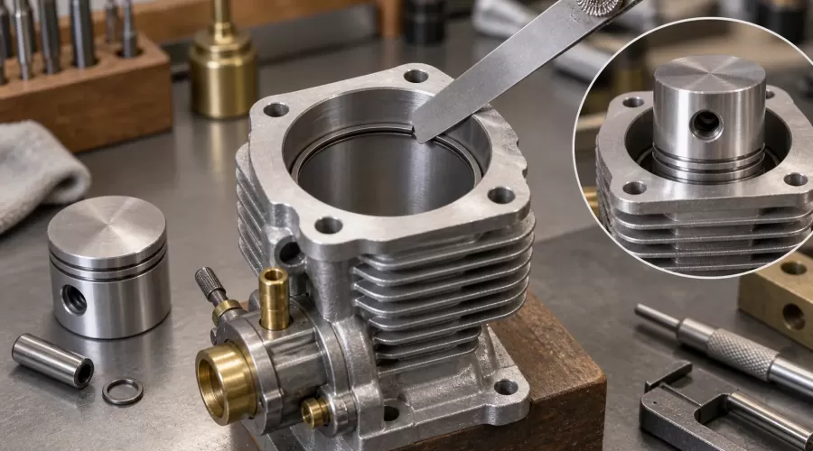
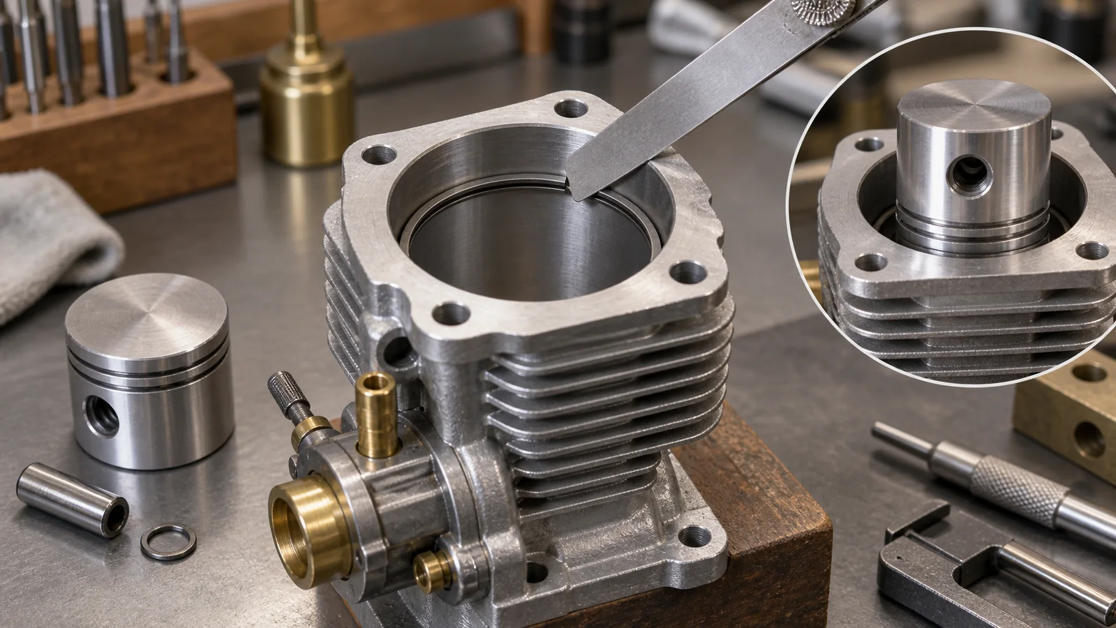
A miniature engine can lose compression through several paths. The inlet or exhaust valve may not seat, the head joint may leak, the ring may not seal, or the test itself may be inconsistent. Seeing a ring through an open cylinder does not tell you which path is responsible. Ring end gap is therefore an inspection result inside a larger evidence chain, not a stand-alone diagnosis.
This guide applies to serviceable piston engines that use one or more split piston rings. It does not establish a universal gap, filing allowance, bore finish, side clearance, ring orientation, torque value, break-in method, or acceptance limit. Miniature glow, gasoline, hit-and-miss, radial, and shop-built engines can use different materials, coatings, groove geometry, lubrication, and operating temperatures. If the maker does not authorize internal service, stop at non-invasive tests and use qualified support.
1. What Piston Ring End Gap Actually Does
A piston ring is not a closed circle. Its two ends remain separated when the ring is compressed into the cylinder. That opening lets the ring be installed and provides room for dimensional change during operation. Combustion heat, wall temperature, ring material, ring position, cooling, fuel, load, and piston design all affect the required allowance.
End gap is only one clearance in the assembly. Do not confuse it with piston-to-bore clearance, ring side clearance in the groove, or ring back clearance behind the ring. A correct end gap cannot compensate for a tapered or out-of-round bore, a worn groove, an incorrectly oriented ring, inadequate back clearance, a distorted piston, or poor surface finish.
The FAA Powerplant Handbook illustrates ring-gap measurement while warning that ring number, type, and arrangement vary by engine make and model. That is the transferable principle: measure the right ring in the right cylinder against the right specification. Aircraft limits do not apply to a desktop engine.
| Measurement | Where it is measured | What it helps evaluate | What it cannot prove alone |
|---|---|---|---|
| End gap | Between ring ends while squared in the bore | Thermal allowance, ring/bore match, wear screening | Complete combustion sealing |
| Piston-to-bore clearance | Specified piston gauge point versus measured bore | Running fit and expansion allowance | Ring condition |
| Ring side clearance | Between ring flank and groove | Freedom to move and groove wear | Bore roundness |
| Ring back clearance | Behind the ring within the groove | Whether the ring can compress without bottoming | Correct end gap |
| Leak-down path | Air heard or measured at inlet, exhaust, or crankcase | Likely leakage route | Exact defective part without follow-up inspection |
2. When to Measure and When to Diagnose First
Measure end gap during an authorized rebuild, after replacing a cylinder or ring set, or when the service procedure explicitly calls for it. For a complete engine that is difficult to start or appears weak, begin with external evidence. Unnecessary disassembly can disturb a good seal, damage a fragile ring, invalidate a warranty, or introduce abrasive dirt.
- Standardize the symptom. Record whether the problem is cold-only, hot-only, sudden, gradual, or present immediately after assembly.
- Verify valve closure and timing. A tight tappet, incorrect cam phase, or valve-seat leak can imitate ring leakage. Use the four-stroke valve timing and lash guide and the valve-seat leak diagnostic guide before assuming the piston must come out.
- Separate compression from leakage. A compression test reflects cranking conditions; leak-down helps locate a static path. Our compression and leak-down guide explains the distinction.
- Check ignition and fuel independently. Incorrect BTDC ignition timing or an unsuitable mixture can produce heat, weak running, or starting symptoms without changing ring dimensions.
- Open the engine only with a service reason. Confirm that parts, drawings, clean tools, and replacement gaskets are available first.
Crankcase leakage during a correctly performed leak-down test makes a piston, ring, or cylinder path plausible, but some leakage is normal and limits are model-specific. A newly built engine may also show a different seal before its approved running-in process is complete. Do not use a finger-over-port impression or propeller “bounce” as a numeric service limit.
3. Establish the Governing Specification Before Touching a Ring
The most important preparation step is deciding whose instruction governs the parts in front of you. Use this hierarchy:
- The current service manual or drawing for the exact engine and revision.
- The instructions supplied with the exact piston and ring set.
- A manufacturer service bulletin that explicitly covers that combination and duty.
- Qualified technical support from the engine, piston, or ring maker.
The Saito four-cycle model-engine manual library demonstrates how specifications are tied to individual model families. Some model engines use a single compression ring; others use different cylinder materials, surface treatments, or multi-cylinder layouts. The presence of a similar-looking ring does not make another engine's number transferable.
A factor expressed as gap per unit of bore is a calculation method, not universal permission. Hastings' performance guidance, for example, provides factors for specified automotive applications and warns that the builder remains responsible for suitability. Use such a factor only when the instructions for your exact supplied ring and piston require it. Never shrink a model-engine target by casually scaling an automotive example.
Before measuring, identify the ring's groove, face marking, bevel, material, coating, and whether it is supplied finished or file-fit. Keep every ring paired with its intended cylinder. Photograph packaging and markings before cleaning them. If the top and second rings differ, do not swap them to make a measurement look better.
4. A Repeatable Piston Ring End-Gap Measurement Workflow
Measurement quality depends on the bore and setup. A feeler gauge cannot rescue a dirty cylinder, a cocked ring, an unidentified wear ridge, or an incorrect measurement depth.
- Make the engine safe. Isolate ignition, remove fuel pressure or fuel supply, let the engine cool, and secure the assembly. Follow the organized bench controls in the model-engine tools and assembly checklist.
- Clean without altering geometry. Remove oil films, carbon flakes, fibers, and grit by the approved method. Do not sand the bore simply to make a ring slide.
- Measure the bare cylinder first. Check diameter, taper, and out-of-round at the manual's locations with suitable calibrated tools. If the bore fails, ring-gap interpretation must include that failure.
- Select and orient the correct ring. Confirm the part number and any top mark or bevel. Insert it gently without twisting or overspreading.
- Square the ring. Push it evenly to the specified depth with a ring-squaring tool or the flat crown/skirt reference approved by the manual. The ring plane must be perpendicular to the bore.
- Measure with clean feeler gauges. Start below the expected size and increase blade thickness until the specified light drag is obtained. Do not force a thick blade between the ends.
- Repeat. Remove, clean, re-square, and remeasure. Record cylinder, ring position, depth, temperature, gauge size, and result.
- Check additional depths only when required. A larger gap near the top than lower in the stroke can point to taper or wear. Do not average unequal readings into a reassuring number.
The Hastings ring-installation guidance explicitly calls for inserting the ring squarely and measuring with a feeler gauge. The Lycoming HIO-390-A1A maintenance manual provides a model-specific example: it pairs each ring with its intended cylinder, squares it with the piston, records the feeler-gauge result, and compares it with the applicable limits. Its aviation values and lubricants do not transfer to a model engine; the useful lesson is that location, pairing, and service context matter.
Do not measure an installed ring by looking through a port, and do not infer end gap from the visible joint on a relaxed ring outside the cylinder. The measurement is defined by the ring compressed and square in the bore in which it will operate.
5. Interpret Tight, Wide, and Changing Gaps
A reading is a comparison to an approved range, not an automatic repair instruction. Interpret it with cylinder geometry, ring identity, service history, and symptoms.
| Observed result | Plausible explanation | Required confirmation | Unsafe shortcut |
|---|---|---|---|
| Below specified minimum | File-fit ring not yet adjusted, wrong ring, undersize bore, burr, or measurement error | Part number, bore size, squareness, maker instructions | Running it hot to “wear in” the ends |
| Above new-part range but below service limit | Finished ring tolerance, mild wear, or approved application difference | Exact new and service limits plus leakage evidence | Replacing parts solely to chase a generic number |
| Above service limit | Worn/tapered bore, wrong or worn ring, damaged cylinder, or mismatched set | Bore metrology, groove condition, ring identification | Installing an arbitrary oversize ring without fit checks |
| Changes materially with depth | Bore taper, ridge, local wear, distortion, or poor squaring | Diameter and roundness at specified depths | Filing to match the largest reading |
| Different among cylinders | Cylinder wear variation, mixed rings, measurement inconsistency | Repeat each labeled ring in its assigned bore | Swapping rings until values look uniform |
A gap that is too small can close as temperature rises. Once the ends butt, the ring can no longer expand normally; loads may transfer into the groove, piston, and cylinder surface. A gap that is too large can reduce the ring's gas-control effectiveness and may accompany increased blow-by, oil contamination, or reduced compression. However, the relationship is not one-to-one. Ring face condition, bore finish, groove clearance, and pressure behind the ring also matter.
Architecture changes the interpretation. A radial engine adds multiple cylinders and a distinctive connecting-rod system; our radial master-and-articulating-rod guide explains that load path. A hit-and-miss engine deliberately alternates firing and coasting under its governor mechanism. Neither behavior is proof of a ring-gap fault. Diagnose the design before judging its sound or cadence.
6. Adjust Only an Approved File-Fit Ring
Many replacement rings are supplied finished. Filing one without authorization can move it beyond the usable range. Proceed only when the packaging or exact technical instruction identifies the ring as file-fit and specifies the target, measurement depth, tool, edge treatment, and acceptance method.
- Confirm the bore has passed its dimensional checks.
- Record the starting gap and the approved target for that ring position.
- Use a proper ring-filing fixture that keeps the ends square.
- Follow the ring maker's direction about filing one end or both; do not improvise.
- Remove very little material, deburr only as instructed, clean the ring, re-square it at the same depth, and remeasure.
- Stop before the target is exceeded. Material cannot be put back.
MAHLE's ring-installation procedure states that its file-fit process removes material from one end while using the unfiled end as a reference. That instruction is authoritative for the rings it covers, not a license to apply the same technique to every miniature ring. If your supplier's directions differ, the supplied directions win.
Reject a ring that is cracked, chipped, distorted, over-filed, incorrectly marked, or no longer sits square. On very small rings, a specialist may be safer than a hand filing attempt. The cost of a replacement ring is usually lower than the cost of a damaged plated cylinder or unavailable piston.
7. Install Without Damaging the Ring System
After measurement, clean the ring, piston, grooves, bore, and tools until no abrasive or filing debris remains. Check ring side clearance and back clearance if the manual requires them. A ring that bottoms in the groove cannot behave correctly even if its end gap is perfect.
Use a ring expander sized for the component. Open the ring only enough to pass over the piston and never spiral it down the grooves. Install directional marks and bevels exactly as specified. Hastings' compression-ring installation guidance explains how wrong groove placement or inverted directional rings can contribute to oil pumping, blow-by, scuffing, and accelerated wear.
Position ring gaps only as the exact instructions require. General diagrams often stagger gaps, but ported two-strokes, pinned rings, single-ring engines, and unusual oil-control systems can impose different rules. Never rotate a pinned ring away from its locating feature or place an end where it can catch a port.
Apply the approved assembly lubricant, use the specified ring compressor or tapered entry, and stop if the piston catches. Do not strike it through resistance. Rotate the assembled engine slowly by hand, verify free movement and valve timing, and complete the specified leak or compression check before fuel operation.
Lubrication requirements are architecture-specific. A live-steam engine uses a displacement lubricator and steam-cylinder oil rather than piston rings in the combustion-engine sense; the model steam-engine lubrication guide explains that separate system. This is a useful boundary when comparing models: similar visible cylinders do not imply interchangeable service methods.
Builders evaluating a serviceable piston-engine project can compare internal-combustion engine models and broader working model engine kits. Product photos and specifications help identify architecture and supplied components, but the current product manual remains the service authority.
8. Symptom-to-Test Decision Table
| Symptom or evidence | Most useful next check | Do not conclude yet |
|---|---|---|
| Hard starting with unknown history | Fuel, ignition, valve motion, timing, and standardized compression | That rings need replacement |
| Leak-down air mainly at intake or exhaust | Valve lash, TDC, cam timing, and valve-seat condition | That end gap is responsible |
| Leak-down air mainly at crankcase | Bore, piston, ring, groove, head joint, and test-method inspection | That a larger gap alone proves wear |
| Compression falls only when hot | Repeat at controlled temperatures; verify clearances and timing against the manual | That thermal ring butting is proven |
| Gap changes from lower to upper bore | Measure taper and roundness with suitable bore tools | That filing the ring will repair the cylinder |
| New ring exceeds the new-part range | Verify bore size, ring part number, coating, and supplier data | That an oversize ring can be fitted safely |
| Correct measured gap but persistent blow-by | Ring face, orientation, groove clearance, bore finish, and seating process | That the end-gap check was useless |
When a multi-cylinder model has one weak cylinder, label every component and compare equivalent measurements without mixing parts. For radial models, also preserve the master-rod and articulating-rod assignments. A clean comparison can isolate one cylinder; an unlabeled teardown can create several new variables.
Frequently Asked Questions
What is piston ring end gap?
It is the clearance between the two ends of a split piston ring while the ring is compressed squarely inside its cylinder at the specified depth. It provides installation and thermal allowance, but it is only one part of the complete piston, ring, groove, and bore fit.
How do I measure ring end gap in a miniature engine?
First verify the clean bare bore for size, taper, and roundness. Insert the identified ring into its assigned cylinder, square it with the approved tool or piston reference at the manual's depth, and measure between the ends with clean feeler gauges. Repeat and record the conditions.
Can I use a gap-per-inch formula from an automotive engine?
Only if the manufacturer of your exact ring and piston explicitly specifies that formula for the application. Materials, coatings, ring position, bore treatment, load, cooling, and operating temperature differ. A full-size automotive factor is not automatically scalable to a model engine.
What happens if piston ring end gap is too small?
The ends can approach or contact each other as the ring heats. If they butt, expansion loads may damage the ring, piston groove, piston, or cylinder. Do not rely on running the engine to wear the ends into clearance.
Does a large ring gap always cause low compression?
No. An excessive gap can contribute to leakage, but compression also depends on the ring face, bore geometry and finish, groove clearances, valve sealing, head joint, test method, temperature, and speed. Confirm the leakage path and compare the measurement with the exact service limit.
Should I file every new piston ring?
No. File only a ring explicitly supplied as file-fit and follow its exact instructions. Many rings are finished parts. Filing without authorization can make a usable ring permanently too wide or damage its end geometry and coating.
Why does the measured gap change at different cylinder depths?
The bore may be tapered, out of round, worn near the top of travel, locally damaged, or the ring may not be square. Repeat the setup and measure bore geometry. Do not average the readings or file the ring to match the largest one.
Conclusion
A reliable ring-gap decision begins with the exact specification and a measured cylinder. Square the identified ring at the required depth, use a clean feeler gauge, repeat the reading, and interpret it with bore geometry and leakage evidence. A tight approved file-fit ring may need controlled adjustment; a wide or changing gap may identify wear, mismatch, or measurement error rather than a filing job. Preserve the distinction between end gap, piston clearance, groove clearance, valve sealing, and ignition timing. That disciplined sequence protects both compression and the small, often irreplaceable components in a working model engine.
References
- FAA — Airframe and Powerplant Mechanics: Powerplant Handbook, AC 65-12A
- MAHLE — Ring Installation Procedures
- Hastings — Engine Building and Ring Installation
- Lycoming — HIO-390-A1A Engine Maintenance Manual
- Hastings — End Gaps for Performance Application
- Saito Seisakusho — Four-Cycle Model Engine Instruction Manual Library
- Hastings — Installation of Compression Rings
Leave a comment