

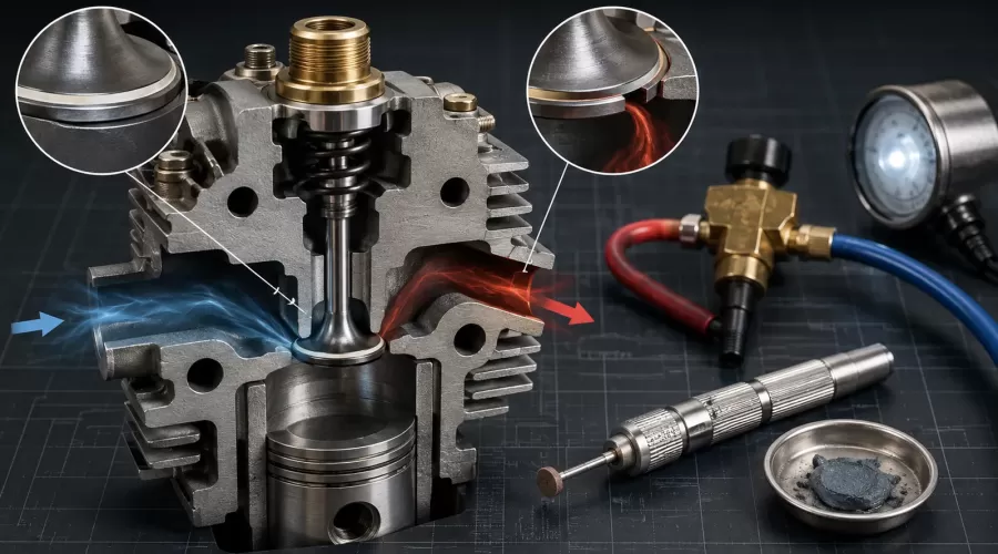
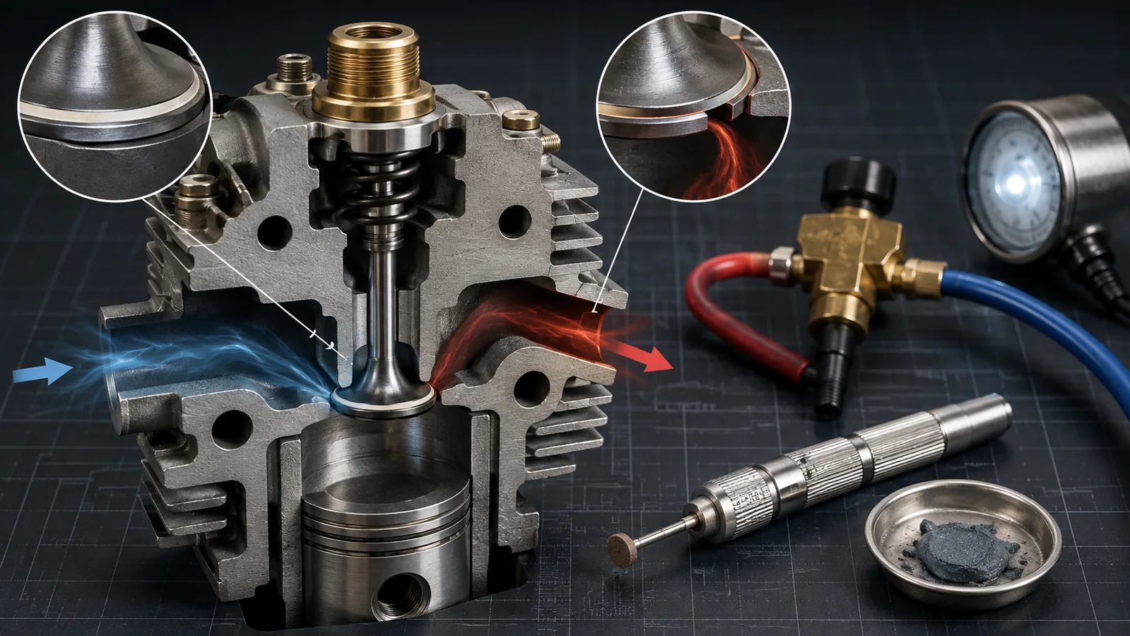
Low compression, difficult starting, fuel mist returning through the intake, or a hiss at the exhaust can make valve-seat leakage plausible. None of those symptoms proves that the seat needs grinding. A tight valve lash setting can hold a sound valve open. Incorrect cam timing can place the piston at the wrong reference point. Carbon, a sticky guide, a bent stem, a damaged margin, a loose seat insert, or a poor test adapter can create similar evidence.
This guide is for small four-stroke model engines with poppet valves. It does not establish universal seat angles, widths, abrasive grades, torque values, leak-down pressures, or acceptance limits. Use the current manual for the exact engine, because materials and geometry vary across glow, gasoline, hit-and-miss, multi-cylinder, and home-machined designs. If the maker does not authorize cylinder-head work, preserve the warranty and obtain service.
1. What Valve Lapping Can and Cannot Do
Lapping is a finishing process. A small amount of controlled abrasive is placed between two mating surfaces and moved so microscopic high spots are removed. On a serviceable valve and seat, this can reveal and refine a narrow, continuous contact band. It is not a substitute for machining.
The distinction matters more as parts become smaller. A few extra strokes that appear harmless on a full-size head can widen the working band substantially relative to a miniature valve. A wide or misplaced band can reduce local seating pressure, alter heat transfer, and mask a concentricity problem. More abrasive may create a larger gray ring while moving the geometry farther from the design.
The Home Model Engine Machinist discussion on valve lapping repeatedly separates light finishing from attempts to correct alignment. It is valuable practitioner evidence, not a specification. The engine drawing and manufacturer's limits remain controlling.
| Condition | Can light lapping help? | Correct next step |
|---|---|---|
| Clean, concentric surfaces with a faint interrupted finish | Possibly, if the manual permits | Use minimal hand finishing and inspect frequently |
| Carbon or gummy residue holding the valve open | Not until contamination is removed | Use the approved cleaning method, then inspect |
| Bent stem or valve head | No | Replace or obtain qualified service |
| Loose or worn guide | No | Measure guide clearance and repair the guide system |
| Seat not concentric with the guide | No | Machine the seat from the correct guide reference |
| Deep pitting, burned edge or inadequate margin | No | Machine or replace according to the manual |
2. Prove the Leakage Path Before Disassembly
Start with the least invasive test. Record the original symptom, fuel, temperature, recent work, and whether the change appeared suddenly or gradually. Work through the model-engine no-start diagnostic sequence so a fuel or ignition problem is not converted into unnecessary cylinder-head work.
- Find true compression TDC. On a four-stroke engine, the piston reaches top dead center twice. Both valves must be in the condition specified for the compression test.
- Check valve motion and lash. Zero or insufficient clearance can hold a valve off its seat. Use the exact model's procedure and the principles in our valve timing and lash guide.
- Standardize cranking evidence. If the manual permits a compression test, use the same adapter, temperature, throttle position, battery state, rotation method, and number of cycles.
- Locate static leakage. If the maker permits leak-down testing, restrain the crankshaft safely at compression TDC, introduce only the approved regulated pressure, and listen at the intake, exhaust, and crankcase paths.
- Repeat. A changing reading is a method problem until proven otherwise.
Lycoming Service Instruction 1191A explains differential compression as a comparison between cylinder leakage and a calibrated restriction with the piston at compression top center. Its aircraft-engine limits do not apply to a miniature engine, but the measurement logic is useful. Our compression test versus leak-down guide explains why the two tests answer different questions.
Air heard at the intake makes an intake-valve path plausible; air at the exhaust makes an exhaust-valve path plausible. Confirm TDC, lash, timing, and tester sealing before opening the head. Air at the crankcase points the diagnosis toward piston, ring, cylinder, or a construction-specific path rather than toward automatic valve lapping.
Briggs & Stratton's current troubleshooting guidance similarly connects improper valve clearance or leakage with compression and starting problems, and recommends leak-down evidence. That supports the sequence, not a direct transfer of mower specifications to model engines.
3. Inspect the Valve, Guide and Seat as One System
Isolate ignition and fuel, let the engine cool, and secure it on a clean bench. Photograph the rocker, pushrod, spring, retainer, shim, and valve orientation before removal. Keep paired valves and components identified. The organized method in the model-engine tools and assembly checklist reduces lost parts and accidental mixing.
Inspect in this order:
- Stem and guide. The valve should move as the manual specifies without binding or obvious side play. A worn guide lets the head approach the seat inconsistently; abrasive cannot repair that reference.
- Valve face and margin. Look for pitting, a burned edge, a thin margin, cracks, impact marks, or a face that no longer appears true.
- Seat surface. Look for carbon, corrosion, impact damage, a discontinuous band, a band positioned too high or low, and evidence that the seat insert has moved.
- Spring and retainer. A damaged spring, incorrect installed height, or retainer interference can prevent normal closing even when the surfaces are sound.
- Cam and lash system. Confirm the valve can fully close after reassembly. Do not use lapping to compensate for a timing or clearance error.
The official O.S. FS-52S manual illustrates why model-specific information matters: it gives a cold valve-adjustment method for that engine and surrounds service with explicit fuel, heat, propeller, and accidental-restart warnings. The values in that manual belong to the FS-52S family, not to every miniature four-stroke.
4. Read the Contact Pattern, Not Just the Color
When the manual permits a contact check, use the specified marking medium or transfer method. Rotate or press the valve only as required to reveal where it touches. A useful pattern is continuous, concentric, and located where the drawing specifies. Its width must remain within the model's limit.
A dark ring is not automatically a good seat. Ask four questions:
- Is the band continuous through 360 degrees?
- Is it concentric with the guide rather than merely matched in one rotational position?
- Is it located correctly on both the valve face and seat?
- Is it narrow enough to meet the drawing or manual after finishing?
The Westerbeke service manual documents checking valve-to-seat contact and uniformity as part of engine inspection. Again, its full-size dimensions are not miniature-engine limits. The transferable lesson is to inspect geometry and contact before declaring that abrasion solved the leak.
If the mark appears on only one side, changes when the valve is rotated, or becomes excessively wide before it becomes continuous, stop. Those patterns point to runout, guide alignment, face error, or previous overworking. Lapping longer can make the surfaces mutually concave or create grooves without restoring the intended reference.
5. A Controlled Hand-Lapping Workflow
Proceed only when the manual permits it and inspection shows a serviceable valve, guide, and seat. Use the abrasive type and grade specified for the materials. Miniature seats may be brass, bronze, steel, cast iron, or an insert; an abrasive suitable for one pairing may embed in or rapidly cut another.
- Protect the guide and engine. Keep abrasive off the stem, guide, ports, cylinder, bearings, and oil passages. If contamination cannot be contained, do not lap in place.
- Apply the minimum amount. A thin film on the working face is enough. More compound does not improve alignment.
- Use hand motion only. Hold the valve with a suitable hand tool or pin vise, apply light axial pressure, and move back and forth as the approved procedure states. Lift and index the valve periodically rather than spinning continuously.
- Inspect early. Clean the surfaces and examine the band after a short interval. The goal is evidence, not a predetermined number of turns.
- Stop at the first acceptable pattern. Continuing after the band is continuous only removes material and widens the seat.
A model-engine case in the HMEM valve-lapping problem thread reports annular grooves after drill-powered rotation and a more consistent finish after switching to gentle manual back-and-forth motion. That is not a controlled laboratory study, but it supports a conservative rule: never use a power drill as a shortcut on a tiny valve seat.
Do not copy an abrasive grade, angle, or turn count from a forum post. The service data for the exact engine determines whether lapping is allowed at all. If the valve or seat needs appreciable material removal, move from a finishing process to the correct machining or replacement process.
6. Stop Conditions: When More Lapping Makes the Engine Worse
Stop immediately and escalate when any of the following appears:
- The contact band remains one-sided or nonconcentric.
- The band reaches the maximum width or wrong position before becoming continuous.
- Deep pits, cracks, a burned margin, a tuliped head, or a bent stem remain.
- The guide has excess clearance, the stem binds, or the valve closes differently after rotation.
- The seat insert is loose, recessed, cracked, or visibly displaced.
- Grooves form, abrasive embeds in a soft material, or the finish becomes less uniform.
- No model-specific service limit or approved procedure is available.
The FAA Aviation Maintenance Technician Powerplant handbook treats valve inspection, guide condition, face and seat work as a controlled system of measurements and approved repair operations. Its aircraft procedures are not instructions for a desktop model. They reinforce the boundary between inspection, finishing, machining, and replacement.
If the head requires seat cutting, face grinding, guide replacement, or concentricity measurement beyond available tools, use a competent model-engine machinist. A miniature part is not lower risk merely because it is small; its tolerances and remaining material can also be small.
7. Clean, Reassemble and Verify the Repair
Abrasive left inside an engine becomes uncontrolled wear material. Clean the valve, seat, guide, ports, head, tools, and bench by the maker-approved method until no residue remains. Do not rely on color alone; inspect crevices and use clean swabs or rinse material as appropriate for the engine's materials.
Reassemble each valve with its original or correctly specified parts. Apply only the approved lubricant at the stated points; the model-engine lubrication guide explains why an arbitrary oil can affect seals, deposits, and measurement. Set valve lash cold or hot exactly as the manual requires, rotate the engine slowly by hand through complete cycles, and verify that both valves close freely.
Repeat the same pre-repair leak or compression test under the same conditions. Compare the leakage path, repeatability, and running symptom, not just one larger number. If sealing improves but the engine still will not start, return to the diagnostic tree instead of lapping again. Fuel, ignition, timing, and load remain separate systems. For a newly assembled engine, follow the exact running-in instructions and use the miniature four-stroke break-in guide as general context.
Document the final contact pattern, parts used, lash, test conditions, and result. This baseline turns a future change into evidence. It also helps the next owner avoid repeating an abrasive process that has already reached its safe limit.
8. Valve-Seat Diagnostic Decision Table
| Evidence | Most useful next check | Do not do yet |
|---|---|---|
| Low compression with unknown test conditions | Standardize and repeat the compression test | Do not remove the head |
| Leak-down air at intake | Confirm compression TDC, intake lash, timing and seat cleanliness | Do not assume the seat needs grinding |
| Leak-down air at exhaust | Confirm exhaust lash, timing, guide motion and contact | Do not blame rings first |
| Continuous narrow pattern and light seepage | Check the manual for permitted light hand finishing | Do not use a drill |
| One-sided or changing contact pattern | Measure guide, stem, face and seat concentricity | Do not lap until the band widens |
| Deep pits, burned edge or thin margin | Use the approved machining or replacement decision | Do not hide damage with abrasive |
| Seal improves but running does not | Return to fuel, ignition, timing and load diagnosis | Do not repeat lapping automatically |
Owners comparing serviceability across architectures can browse working model engine kits and the hit-and-miss engine collection. Category placement and product photographs help identify a layout, but they do not establish a valve-service specification. Always match the current manual, serial revision, materials, and supplied components.
Frequently Asked Questions
Does valve lapping fix low compression in a model engine?
Only when a confirmed valve-seat leak comes from minor surface mismatch on otherwise serviceable, concentric parts and the manufacturer permits lapping. Low compression can also come from valve lash, timing, rings, cylinder condition, a head seal, decompression hardware, or the test method.
Can I lap a miniature engine valve with a drill?
No. Continuous powered rotation can cut grooves, remove material too quickly, widen the seat, and hide a concentricity problem. Use only the model-approved hand method, light pressure, short intervals, and frequent inspection.
How do I know which valve is leaking?
With the piston securely at compression top dead center and the correct regulated leak-down procedure, air at the intake suggests an intake-valve path and air at the exhaust suggests an exhaust-valve path. Confirm lash, timing, and tester sealing before disassembly.
What grit should I use to lap a model-engine valve?
Use only the abrasive type and grade specified for the exact valve and seat materials. There is no universal grit. A compound suitable for hard steel may cut or embed in a soft brass or bronze seat differently.
Should the contact band be wide or narrow?
It should match the exact drawing or service limit and be continuous, concentric, and correctly positioned. Do not copy a width from another engine. A band that becomes too wide before sealing is a stop condition, not permission to keep lapping.
How do I remove all lapping compound?
Follow the maker-approved cleaning method for the materials and coatings. Disassemble enough to keep abrasive out of guides, ports, cylinders, bearings, and oil passages; clean repeatedly and inspect swabs or rinse material until no residue remains.
When does a valve seat need machining instead of lapping?
Machining or replacement is indicated when the seat is off-center, too wide, misplaced, deeply pitted, cracked, loose, or paired with a bent valve, damaged margin, or worn guide. Lapping cannot restore those geometric references.
Conclusion
A good valve-seat repair begins with a located leak and ends with a repeatable verification. Confirm compression TDC, lash, timing, guide condition, and contact geometry before touching the seat. If light hand lapping is authorized, use the minimum abrasive and stop at the first acceptable pattern. Bent, worn, off-center, burned, cracked, or over-wide parts need the correct machining or replacement decision. That discipline protects both compression and the small amount of material available in a miniature engine.
References
- Lycoming Service Instruction 1191A — Cylinder Compression
- Briggs & Stratton — Small Engine Problem Solving Tips
- O.S. Engines FS-52S Instruction Manual
- Westerbeke Service Manual — Engine Inspection and Valve-to-Seat Contact
- FAA Aviation Maintenance Technician Handbook — Powerplant, Volume 2
- Home Model Engine Machinist — Valve Lapping Discussion
Leave a comment