

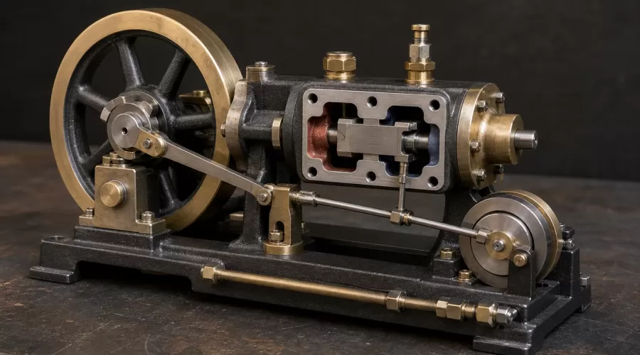
Quick answer: Correct model steam engine valve timing is not found by guessing one eccentric angle. First make the cold mechanism free and identify the exact valve type and intended direction. Then center the slide valve so the two cylinder ports open by equal amounts at opposite ends of valve travel. Only after that should you set the eccentric phase so the correct admission port is just beginning to open as the piston crosses each dead center. Recheck both ends, turn the engine through several complete revolutions by hand, and use only the maker's approved low-energy commissioning method before connecting a boiler.
Key takeaways: equal valve travel and correct event timing are different tests; 90 degrees is a geometric reference, not a universal finished setting; lap, lead, admission type and rod geometry change the required advance; and a steam engine that runs in the wrong direction may have phase rather than centering trouble. Valve centering and eccentric phase are two separate adjustments; changing one cannot reliably correct the other.
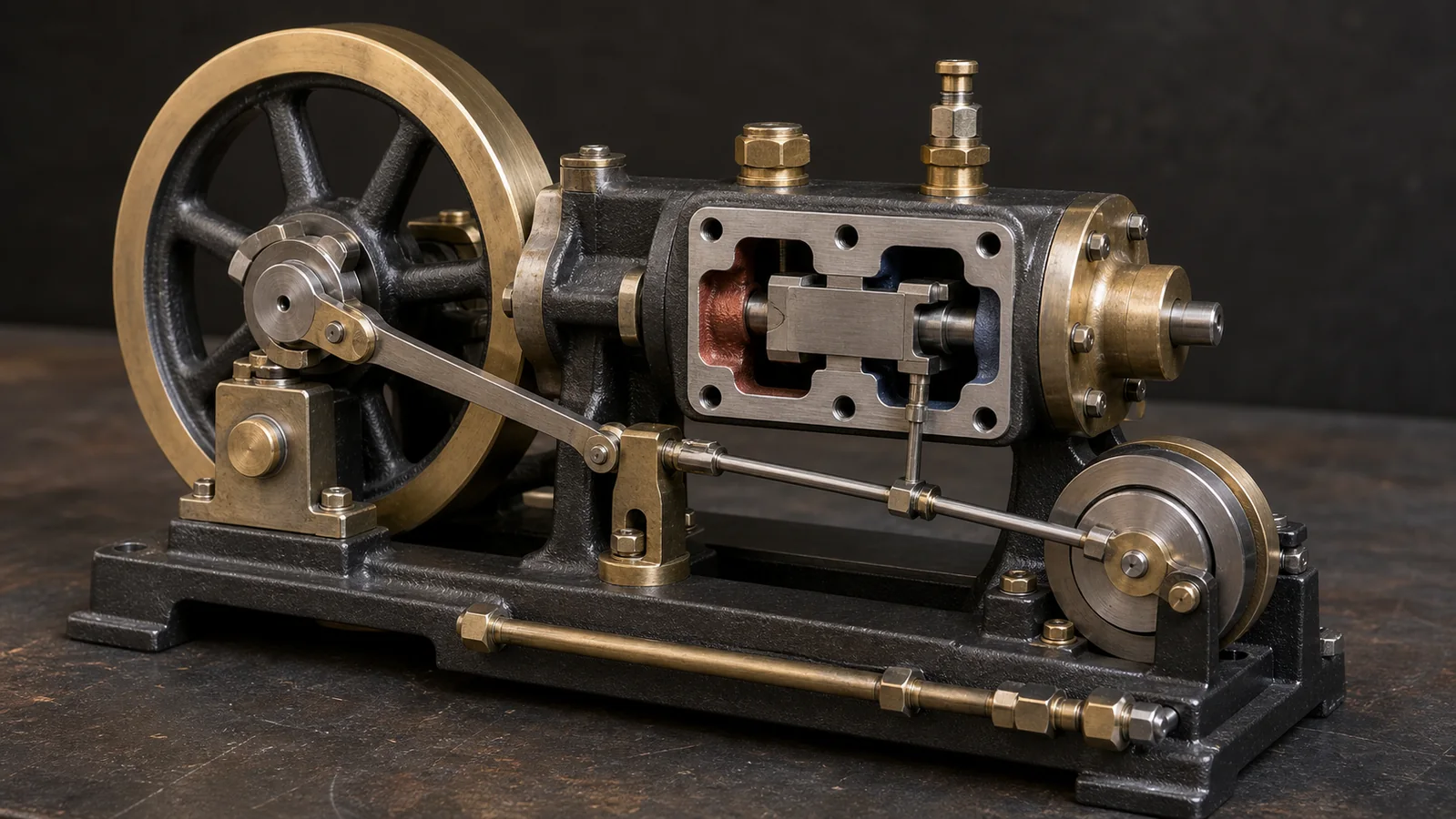
Reviewed: August 31, 2026. This guide synthesizes a Stuart Models timing sheet, Smithsonian mechanism documentation, established model-engineering references and conservative HSE pressure-system guidance. The drawing and instructions supplied with your exact engine override every generic relationship described here.
What model steam engine valve timing controls
A double-acting steam cylinder needs a valve to connect one end of the cylinder to live steam while the other end can exhaust. Half a revolution later, those jobs swap. The archived engineering text Steam-Engine Principles and Practice documents slide valves, eccentrics, dead centers and valve-setting methods: the eccentric moves the valve so inlet and exhaust events alternate at the two ends of the cylinder.
The crank converts piston force into rotation. Near top or bottom dead center, however, the crank and connecting rod are almost in line, so cylinder pressure produces little starting torque. The flywheel carries the mechanism through that region once it is moving. A single-cylinder engine may therefore need a hand start even when its timing is correct. Failure to self-start from every crank position is not proof of a timing fault.
Timing determines when each port begins to admit steam, when admission ends, and when exhaust opens. If events are late, the engine may hesitate, reverse unexpectedly or need excessive pressure. If events are too early, the engine may work against itself, sound harsh or waste steam. Binding, leakage, poor lubrication and condensate can produce similar symptoms, so use the broader model steam engine troubleshooting guide before moving an eccentric that was previously correct.
Valve centering and eccentric phase are different adjustments
Adjustment 1: center the valve travel
Centering asks whether the valve travels equally across the two end ports. With the steam-chest cover removed and the mechanism rotated by hand, compare the maximum admission opening at one end with the maximum opening at the other. On many simple engines, valve position on its rod or the effective linkage length changes this balance. The eccentric may be at an arbitrary phase while this first check is made because the goal is travel symmetry, not event timing.
The Stuart Models slide-valve timing sheet describes checking equal port openings and correcting the valve location before final timing. Measure the visible opening, not merely the distance from the valve to the steam-chest wall. The casting or cover may not be perfectly concentric with the port face.
Adjustment 2: set the eccentric phase
Phasing asks whether the centered valve reaches the required position at each piston dead center. The eccentric is effectively a small crank whose throw drives the valve. Rotating the eccentric on the crankshaft advances or retards all valve events without fixing an off-center valve. The expected position depends on the engine's intended direction and whether the valve uses outside or inside admission.
This separation prevents circular troubleshooting. If one port opens much farther than the other, correct centering first. If both openings are equal but the wrong port opens at dead center, correct phase. Repeating small changes to both adjustments at once destroys the diagnostic baseline.
Dead center, lap, lead and angle of advance
Dead center is the crank position at either end of the piston stroke. A broad visual estimate can be misleading because the piston moves very little while the crank sweeps several degrees around dead center. Use the maker's timing marks, a dial indicator, a temporary pointer and degree disc, or the equal-offset method specified for the engine. Always approach a reference position in the normal direction of rotation so backlash is taken up consistently.
Valve travel is the full distance the valve moves. For a simple eccentric drive, eccentricity is half the theoretical valve travel before linkage geometry is considered. The Slide Valve, Simply Explained describes the eccentric as the practical equivalent of a small crank and connects eccentricity with valve motion.
Lap is the amount by which a valve face overlaps a port when the valve is at mid-travel. Steam lap allows admission to close before the piston reaches the end of its stroke, so the trapped steam can expand. Lead is the small opening that may exist at dead center. Some simple models are designed with little or no lead; other engines deliberately use it. Do not file a valve or port to create a value copied from another design.
Angle of advance is the eccentric's phase beyond a right-angle relationship to the crank. The Model Engineer's Handbook links lap and advance to steam distribution. A statement such as "set it at 90 degrees" omits lap, lead, admission type and rod angularity. Treat 90 degrees as a conceptual baseline only. The final setting belongs to the drawing.
How the evidence was evaluated
Manufacturer information receives priority for model-specific sequence and geometry. Museum and established engineering references support the mechanism and terminology. The specialist Model Engineer timing discussion adds practical observations about separating valve centering from eccentric phase, but individual forum angles and pressures are not transferred to unrelated engines.
A recent r/modelengineering first-run post reported that a Paddleduck engine running on air still needed leakage, timing and gland work. That is a useful demand signal: builders are actively commissioning mechanisms and distinguishing multiple unfinished systems. It does not prove that one timing method, pressure or angle fits all models.
The resulting method is intentionally conservative: identify, record, center, phase, rotate by hand, verify with the lowest-energy maker-approved source, and only then consider steam. It does not certify a boiler, redesign valve gear, prescribe a universal lead, or replace the engine's drawing.
Cold safety gate before touching the eccentric
Disconnect the engine from the boiler or isolate it exactly as the maker directs. Remove the heat source. Confirm zero pressure and allow all parts to cool. Release stored compressed-air pressure before opening a steam chest, loosening an eccentric or placing fingers near the linkage. The UK Health and Safety Executive advises isolating equipment containing steam or compressed air and releasing stored energy before maintenance in its work-equipment maintenance guidance.
Keep the flywheel stationary while tightening a grub screw. Use eye protection appropriate to the maker's procedure. Do not hold an engine in one hand while applying air with the other. Mount the engine securely, fit a guarded hose and regulator approved for the source, and keep hair, sleeves and tools clear of the flywheel.
For a complete plant, read the model steam boiler water-level and priming guide and service the displacement lubricator separately. HSE research report RR1177 explicitly discusses risk control for small pressure vessels including model steam engines. Local rules and club inspection requirements may apply.
Step-by-step slide-valve timing workflow
1. Freeze the known baseline
Photograph the crank, eccentric, valve rod, reversing lever and any timing marks. Mark the current eccentric position with a removable fine line. Record which way the flywheel is intended to turn when viewed from the timing side. If the engine ran correctly before dismantling, this evidence is more valuable than a generic diagram.
2. Confirm free cold motion
Turn the flywheel slowly through several revolutions with no pressure connected. Feel for a repeating tight spot. Disconnect the valve rod only if the drawing allows it, then compare the engine side and valve side separately. Correct a bent rod, overtight gland, dry bearing or mechanical contact before adjusting timing. Use the maker's lubricant at named external points; the broader model engine lubrication guide explains why more oil is not a substitute for alignment.
3. Identify the valve and admission type
Confirm that the component is a D slide valve, piston valve, oscillating cylinder, rotary valve or another system. A conventional outside-admission D valve and an inside-admission piston valve do not use the same visual port relationship. If the steam chest cannot be opened without disturbing a critical seal, stop and use the manufacturer's indirect timing procedure.
4. Establish both piston dead centers
Find the two end positions accurately and mark them temporarily. Approach each point in the intended running direction. A simple pointer and degree disc can make repeated observations consistent, but do not rely on a piston that appears to stop moving over a broad arc. Backlash must be taken up in the same direction for every comparison.
5. Center the valve
Rotate the mechanism until the valve reaches maximum travel toward one end and measure the corresponding port opening. Rotate to the other extreme and compare. Adjust only the valve position or specified linkage length until the maximum openings match as closely as the drawing requires. Tighten the adjuster lightly, rotate again, and confirm that tightening did not shift the result.
6. Set an initial eccentric phase
Place the piston at the specified dead center. Loosen the eccentric only enough to rotate it without damaging the shaft. Turn the eccentric in the intended direction until the drawing's named admission port is just beginning to open, or until the specified lead is present. Lock the eccentric gently. Never assume which edge is admission without tracing the live-steam and exhaust passages.
7. Check the opposite dead center
Rotate the flywheel 180 crank degrees in the normal direction to the opposite piston dead center. The opposite admission event should match the maker's requirement. If one end leads and the other lags while maximum port openings remain equal, split the difference only when the engine instructions specify that method. Connecting-rod and eccentric-rod angularity can prevent perfect symmetry on some designs.
8. Complete a full hand-rotation audit
Turn at least two full revolutions and watch admission, cutoff and exhaust sequence. Verify that no valve, rod or eccentric strap reaches a hard stop. Recheck grub-screw security and shaft position. Refit the steam-chest cover with the correct gasket and tightening pattern. A correctly timed but leaking chest can still fail its first test.
| Checkpoint | Observation to record | Adjustment family |
|---|---|---|
| Maximum opening, end A | Measured visible port opening | Valve centering |
| Maximum opening, end B | Measured visible port opening | Valve centering |
| Dead center A | Named port closed, cracking open or specified lead | Eccentric phase |
| Dead center B | Opposite named port at matching specified event | Eccentric phase |
| Two full revolutions | No bind, collision or loose fastener | Mechanical assembly |
Cold compressed-air verification without creating a new fault
Compressed air is useful because it allows a cold check, but it does not duplicate steam. Air does not condense and expand like steam, and a leak that seems minor on air may behave differently when hot. Use only the engine manufacturer's approved regulator, connection and test range. If no safe test method or limit is supplied, ask the maker or an experienced model-engine club rather than inventing one.
Start with the regulator closed and the engine secured. Stand clear of the flywheel plane. Introduce the minimum flow needed to observe direction and continuity, then close the supply before any adjustment. Do not loosen the eccentric while air is connected. Record whether the engine starts with a gentle hand turn, runs evenly through both strokes, maintains the intended direction and exhausts from the expected connection.
A single-cylinder engine can stop on dead center even when correctly set. Rotate it away from dead center and try the same controlled start again. If it repeatedly kicks backward, closes the wrong port or requires a large hand force, return to the cold phase check. If it slows at the same crank angle with the valve rod disconnected, investigate the mechanical side instead.
Timing symptom matrix
| Observation | Most useful distinction | Safe next check |
|---|---|---|
| One end port opens farther than the other | Valve travel is off-center | Correct valve position or linkage length before moving eccentric phase |
| Equal maximum openings, but admission is late at both ends | Centering may be correct; phase is retarded | Compare both dead-center events with the drawing |
| Engine consistently runs backward | Eccentric phase or reversing-gear selection may match the opposite direction | Confirm intended direction and admission type before changing anything |
| Tight spot remains with valve rod disconnected | Fault is not created by valve timing | Inspect crank, bearings, crosshead and alignment |
| Runs on air but poorly on steam | Heat, condensation, lubrication or leakage may be involved | Check water level, drains, lubrication and seals; do not keep advancing timing |
| Harsh knock near each dead center | Possible excessive lead, liquid carryover, backlash or mechanical contact | Stop immediately, isolate and inspect cold |
Do not tune by sound alone. Repeat the same observation after only one controlled change. A written worksheet prevents a sequence of undocumented adjustments from moving farther away from the design setting.
Reversing engines, slip eccentrics and other special designs
A reversing engine may have two eccentrics, a Stephenson link, a slip eccentric or a valve that changes admission and exhaust functions. The neutral or mid-gear position adds another geometry check. Follow the reversing-gear drawing and verify both forward and reverse settings separately. The RETROL SE02 reversible steam engine system illustrates why intended direction is part of the product configuration, not merely a flywheel preference.
Marine installations add shaft alignment, propeller load and access constraints. Review the marine steam engines and boilers category and a representative twin-cylinder marine steam engine to see how multi-cylinder layouts can reduce dead-center starting behavior while increasing linkage complexity.
Oscillating cylinders and rotary valves do not use the same D-valve workflow. Do not open, file or reposition a component merely because it occupies the place where a slide valve would be expected. Compare your mechanism with the exact parts diagram. Browse model steam engines and live-steam engines and boiler models to understand the range of valve and plant architectures.
When not to adjust valve timing
Leave the eccentric baseline intact if the engine previously ran correctly and the new symptom began after a fuel, water, lubrication, hose, regulator or mounting change. Do not adjust timing to compensate for a blocked port, leaking gasket, loose flywheel, bent valve rod, overtight gland, seized bearing or low boiler water. Repair the root cause first.
Stop and seek model-specific help if timing marks conflict with the drawing, the valve cannot travel without contact, the crankshaft is visibly damaged, a pressure component is homemade or unknown, or a safety valve has been altered. This guide cannot approve pressure equipment or modified valve gear.
Frequently asked questions
Is a steam-engine eccentric always set 90 degrees from the crank?
No. Ninety degrees is a geometric baseline for a simple zero-lap relationship. Lap, lead, admission type, intended direction and rod geometry commonly require a model-specific angle of advance. Use the drawing.
How do I know which steam port should open at top dead center?
Trace the live-steam and exhaust passages and use the manufacturer's timing diagram. Outside-admission and inside-admission valves can reverse the visual relationship, so appearance alone is unreliable.
Should I center the slide valve before setting the eccentric?
Yes for the conventional workflow described here. First make maximum opening at the two end ports equal, then set the eccentric phase at dead center. Recheck both after tightening.
Can I time a model steam engine with compressed air?
Compressed air can support a cold functional test when the maker provides a safe connection and limit. It does not reproduce steam condensation, expansion, heat or lubrication. Never adjust the engine while pressure is connected.
Why does a correctly timed single-cylinder engine need a hand start?
The crank can stop near dead center, where cylinder force creates little turning moment. A gentle hand start may be normal. Persistent reverse kick, binding or wrong-port admission still requires diagnosis.
Can valve timing fix a model steam engine that binds?
Only if the valve or linkage itself causes the bind. Disconnect the valve drive only as the drawing permits and compare both sides. A crank, bearing, crosshead or alignment fault needs mechanical correction.
Does more lead always make a model steam engine start better?
No. Excessive lead can make the engine work against itself or run harshly. Some designs use little or no lead. Never copy a lead value from another engine.
Conclusion
A reliable timing job begins by refusing to treat every symptom as an eccentric-angle problem. Confirm free cold motion, identify the valve and direction, establish both dead centers, center the valve travel, and only then set phase. Verify both ends after tightening and use the lowest-energy maker-approved commissioning method. This sequence preserves evidence, limits unnecessary changes and makes the final steam test safer and more informative.
References
- Stuart Models: Slide Valve Timing
- Steam-Engine Principles and Practice: Slide Valves and Their Setting
- The Model Engineer's Handbook
- Model Engineer: Steam Engine Timing
- Project Gutenberg: The Slide Valve, Simply Explained
- HSE: Maintenance of Work Equipment
- HSE RR1177: Risk Control for Small Pressure Vessels
Leave a comment