

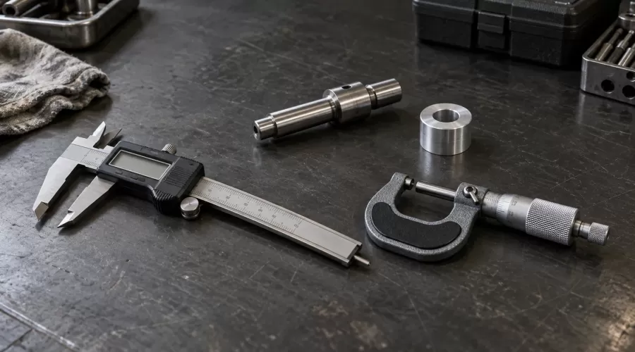
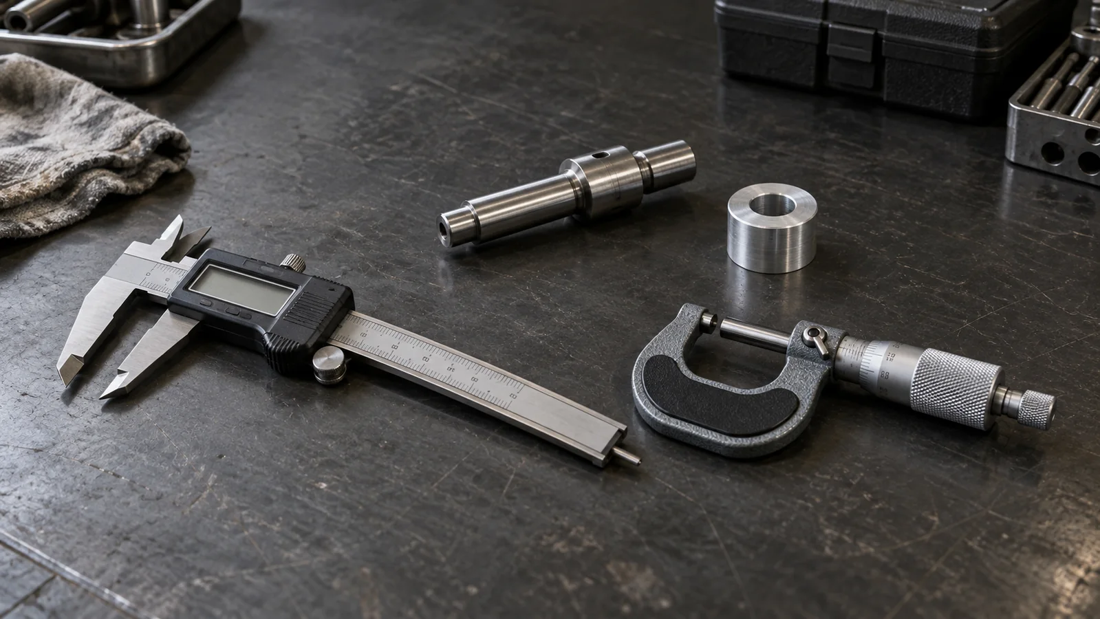
Quick answer: Use a caliper for accessible general dimensions and initial part identification. Consider a suitable micrometer when an outside dimension requires tighter control, but check its range, contact geometry, condition and specification first. Neither instrument proves a bearing fit, cylinder clearance or replacement compatibility merely by displaying extra decimal places. Choose the method from the feature and its documented acceptance requirement, not from the tool's price or screen resolution.
A miniature engine makes a small measuring error look important very quickly. A spacer seems only slightly thicker, a shaft looks the same diameter, or two bearings appear interchangeable. The useful question is not simply which tool is more accurate. It is whether the complete measurement can answer the decision you are about to make. This guide helps a bench builder separate identification, comparison and acceptance without inventing service limits for an engine.
Key takeaways
- Write down exactly which feature you intend to measure.
- Read resolution, stated accuracy and repeatability as different things.
- A zero check is necessary but is not a complete calibration.
- Contact shape and access can rule out an otherwise precise instrument.
- Uncertain measurements are a reason to improve the method, not to force assembly.
Start with the decision, not the display
Identification asks whether a removed part belongs to a broad size family. Comparison asks whether one part differs from another under a controlled method. Acceptance asks whether a feature meets a documented requirement. These jobs can need different equipment even when they concern the same piece of metal. A caliper may identify a shaft size family while being unsuitable for deciding whether a close-fitting bearing seat remains within its permitted limits.
Record the manufacturer, engine model, version and part location before measuring. A diameter alone cannot identify material, heat treatment, closure arrangement or intended fit. If you are starting a build, use the model-engine assembly tools checklist to organize the job. A measuring instrument supplements the correct drawing and instructions; it does not replace them.
The F-A-R record connects feature, acceptance requirement and repeatability before a model-engine measurement decision. Feature means the exact surface and direction being checked. Acceptance requirement means the specification or decision boundary you actually possess. Repeatability means what happens when you release, reposition and measure again. If any of these is missing, keep the result descriptive rather than calling a part good or bad.
Sketching the feature often exposes ambiguity. “Spacer thickness” could mean its flat overall thickness, the height of a shoulder, or the distance between two contact faces. “Shaft diameter” could refer to a bearing seat, a seal track or a worn section. Mark the location on a photograph or simple sketch. That small preparation prevents a precise number from describing the wrong feature.
Resolution is not a promise of accuracy
The last displayed digit tells you the instrument's reading increment. It does not establish the error of the complete result. A repeatable number can still contain a consistent offset. Conversely, a calibrated instrument may produce scattered readings when the workpiece moves or contact pressure varies. These distinctions matter most when the proposed assembly decision is close to a limit.
NIST's traceability guidance explains that a traceable result is not automatically fit for its purpose: uncertainty still needs to suit the measurement need. For a workshop, the practical implication is straightforward. Do not accept a close-tolerance feature solely because the instrument has a calibration label. Check whether the method, range and uncertainty can support that particular decision.
The JCGM international vocabulary work hosted by BIPM provides the terminology framework for metrology. Use that distinction in your own notes: a resolution entry, a calibration reference and a repeat-reading range describe different aspects of a result. Writing only “digital, therefore accurate” removes information you may need later.
Choose the contact geometry before the instrument family
| Feature and purpose | Possible starting method | Important boundary |
|---|---|---|
| Overall length or accessible width | Caliper | Jaw alignment and the actual contact faces |
| Accessible outside shaft diameter | Outside micrometer for closer evaluation | Range, anvil geometry and documented requirement |
| Small bore or recessed diameter | Appropriate bore method | An outside micrometer cannot reach an internal feature |
| Groove or thin wall | Specialized contacts if required | Ordinary flat anvils may bridge the feature |
| Flexible seal cross-section | Material-appropriate low-force method | Compression can change the dimension |
| Endplay or runout | Suitable indicator arrangement | A diameter reading is not displacement or runout |
A conventional outside micrometer measures between its anvil and spindle. It is useful only when those surfaces can contact the intended feature correctly. Narrow grooves, rounded walls and recessed shoulders may require different contacts or a different method. Starrett's micrometer overview distinguishes outside, inside, depth and specialized designs. That variety is a reminder to select by geometry, not simply by the word micrometer.
Calipers offer flexible access for many initial checks, but outside jaws, inside jaws, a depth rod and step faces are not identical measurement arrangements. A check that is satisfactory for one function does not establish performance for every other function. Read the actual instrument instructions and specifications rather than borrowing a tolerance from an unrelated model or a generic comparison chart.
For bearing-related work, distinguish identification from fit assessment. The bearing clearance, endplay and preload guide explains why those are different questions. A shaft diameter measurement is only one part of the evidence. It does not tell you a bearing's internal clearance or whether an assembled shaft has the correct axial movement.
A repeatable bench routine
First make the assembly safe. Stop the engine, isolate starting power and allow hot parts to cool before handling. Do not measure rotating machinery. Keep fuel, abrasive debris and loose tools away from the measuring area. Remove a part only through the engine's documented procedure; this article is not permission to dismantle a pressure system or remove a retained component by force.
Inspect the measuring faces and the intended workpiece surfaces. Dirt, a burr or a damaged edge can become the contact point. Clean using a method suitable for the material and instrument. Do not sand a seat or flatten a burr merely to improve a reading; altering the part changes the question and may destroy useful evidence about the original condition.
Check units, zero and instrument condition. Follow the maker's procedure for any setting standard or reference check. If a tool was dropped, damaged or stored badly, a closed-jaw zero alone cannot establish that it is trustworthy throughout its range. Use an appropriate calibration or service route when the decision warrants it. Keep instrument identity and the relevant certificate or reference with the result.
Take a reading, release contact, reposition and repeat. Keep contact gentle and consistent. Mitutoyo's caliper technique guidance emphasizes light force, alignment and repeated measurements. Do not squeeze harder to make the number settle. For a micrometer, use its prescribed force-control procedure rather than tightening the spindle as if it were a clamp.
Write down all the observations, including suspicious ones. Investigate why they differ before discarding them. Your method should establish a stable contact condition, not select whichever reading makes a replacement seem acceptable. If another operator obtains a different range, compare the measuring location, contact force and orientation before assuming that either person's instrument is defective.
Temperature and handling conditions deserve a note, especially when a part has just been machined, run or held in a warm hand. Let the work settle under suitable conditions instead of converting a hot reading into a cold specification by guesswork. The NPL dimensional metrology overview places length measurement within a much broader measurement infrastructure; a workshop reading is not equivalent to a laboratory result merely because both use millimetres.
Three illustrative decisions
Example one: sorting spacers. Suppose two loose spacers appear interchangeable, and the purpose is initially to separate visibly different lengths. A caliper may provide a useful first comparison if both have clean, accessible contact faces. Record each part separately. If the assembly drawing subsequently requires a tightly controlled stack height, revisit the method rather than treating the sorting result as a final acceptance measurement.
Example two: a borderline shaft. Imagine a hypothetical drawing gives an allowed interval of 4.990–5.000 mm. Those numbers are an invented teaching example, not an EnginesDIY engine specification. A displayed 4.999 mm does not settle the decision if the complete measurement's uncertainty could cross the limit. Improve or commission the measurement and use an appropriate decision rule; do not choose a tighter-looking tool and assume the question is solved.
Example three: a flexible ring. A seal can change shape under contact pressure, so a metal-part routine may produce misleading dimensions. Use the O-ring size measurement guide for that material-specific question. A micrometer's finer display does not automatically make it the right tool for every soft part.
These examples share one stopping rule: when the method cannot distinguish the alternatives reliably, stop the acceptance decision. You can still photograph the part, record markings and ask the supplier for the correct drawing. Progress means reducing uncertainty before an irreversible choice, not collecting more digits from the same unsuitable setup.
Do not confuse dimensions with function
A roundness concern is not settled by one diameter. A runout concern depends on a reference axis and setup. An alignment concern depends on the relationship between components. For the latter, read the shaft coupling alignment guide. Avoid using a convenient caliper reading to answer a different mechanical question.
Likewise, screw length identification does not determine safe thread engagement. A depth measurement may require a clear reference face and an understanding of what lies inside the hole. The screw length and bottoming guide addresses that assembly boundary. No measurement here authorizes replacing an original screw with a longer one.
If you are selecting a project from the model-engine kits category, compare its documented assembly needs with your available tools before ordering. Ask about the exact version and instructions when a listing leaves that unclear. This category link is a route to projects, not an assertion that a particular tool, bearing or spacer is included or compatible with every kit.
A useful measurement record
Keep a short record containing part identity, feature sketch, instrument identity, units, range, zero or reference check, repeated readings, relevant conditions, requirement source and final decision. Include a photograph that shows where contact occurred. That record is more valuable than a single number in a message because another person can see what the result does and does not describe.
Separate measured values from conclusions. “Readings were within this interval under this setup” is an observation. “Part meets the drawing” requires a justified acceptance method. “Replacement fits this engine” additionally requires the correct part identity and assembly specification. Preserve the original raw observations even if a later, better method changes your conclusion.
Frequently asked questions
Is a micrometer always better than a caliper?
No. A suitable micrometer can help with close outside dimensions, but range, contact geometry and the requirement determine suitability. It cannot replace an inside or displacement method when the feature needs one.
Does a 0.01 mm display mean 0.01 mm accuracy?
No. Display increment is not the error or uncertainty of the complete measurement. Read the instrument specification and assess the actual setup before making an acceptance decision.
Is checking zero enough?
No. Zero checks help detect problems, but do not establish performance across the range or for every contact arrangement. Use the maker's reference-check and calibration guidance.
Can I measure a small bore with ordinary caliper jaws?
Possibly for an initial check when the jaws can contact correctly, but suitability for a close-tolerance decision is not automatic. Small or recessed features can require a different bore method.
Should I average readings that disagree?
Investigate alignment, location, force and surface condition first. Averaging cannot remove a systematic setup error or make the wrong contact geometry suitable.
Can dimensions alone confirm replacement compatibility?
No. Material, version, function, full designation and assembly requirements can matter alongside dimensions. Use exact-model documentation or a verified supplier part record.
When should I stop and ask for help?
Stop when the requirement is unknown, readings remain unstable, a part is damaged, or uncertainty could change the acceptance decision. Obtain the drawing or a suitable measurement before forcing or modifying the assembly.
Conclusion
Start with the feature, obtain the requirement and establish repeatability. A caliper is a flexible starting tool; a micrometer is a specialized choice, not an automatic guarantee. The right method gives enough evidence for the decision while preserving the part, the instructions and a useful record of what was actually observed.
Leave a comment