

By EnginesDIY Editorial Team | Published and reviewed September 23, 2026
Quick Answer
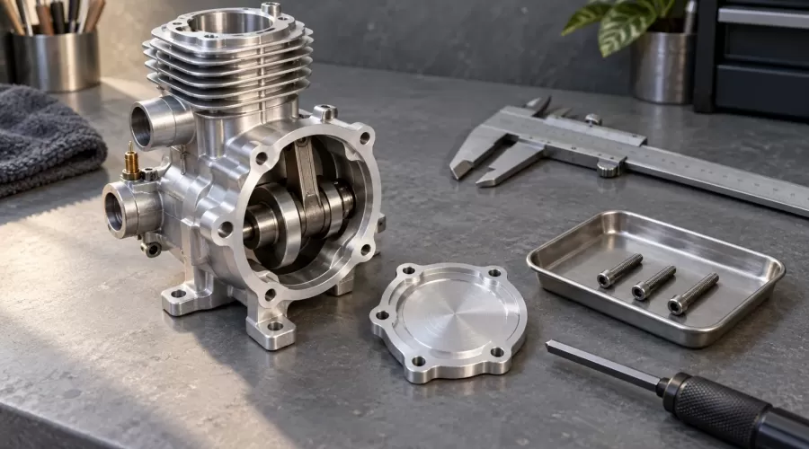
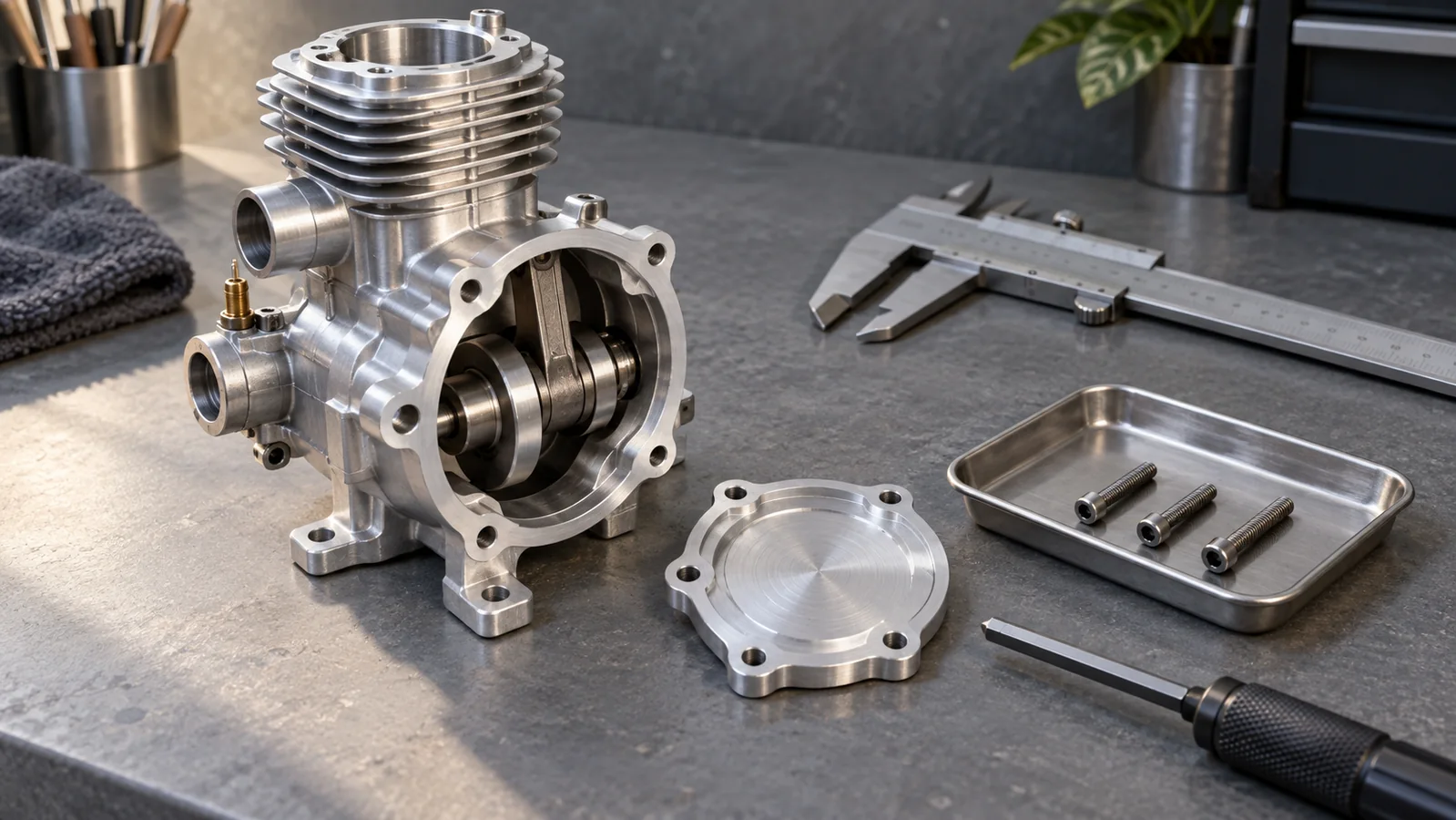
A model-engine screw can feel tight without clamping the part. It may reach the bottom of a blind hole, jam against incomplete threads, bind on the wrong pitch, or stop at an unthreaded shoulder. Check the correct screw, actual clamped stack and usable threaded depth before applying the specified torque. A longer screw is not automatically stronger, and a shorter screw is not automatically safe.
The S-E-C record separates clamped stack, effective engagement and bottom clearance. Record S for the assembled stack and head seat, E for the overlap of usable mating threads, and C for the clearance to the hole bottom or nearby moving part. This is an editorial diagnostic worksheet, not a manufacturer-approved design calculation. If the engine drawing or replacement specification is missing, obtain it before tightening, cutting a screw or modifying a hole.
Key takeaways
- Match diameter, pitch, length, head, material and the exact installation location. A shared hex-key size does not identify a screw.
- Distinguish the depth of a drilled hole from the depth of fully usable internal threads.
- Account for the actual cover, bracket, gasket and specified washer stack. A missing component changes screw penetration.
- High turning resistance is not proof of clamp load. Do not use more leverage to diagnose it.
- A clean, aligned joint must still meet the maker's engagement, clearance and tightening instructions.
- Stop for cracked bosses, damaged threads, unknown critical fasteners or contact with rotating parts.
Which screw length are you measuring?
Start with the part drawing rather than the parts tray. A typical socket-head cap screw is measured from its bearing surface under the head to its tip. A flat countersunk screw normally includes the head in its nominal length because that head enters the part. Special shoulder screws and unusual head forms need their own dimensional reference. Bolt Depot's measurement guide illustrates these different starting points and explicitly notes exceptions.
That distinction matters when an apparently identical replacement is a little longer below the seating surface. A counterbore also changes where the head bears: measure the stack below the actual seat, not simply the outside thickness of the cover. Record what you measured in a sketch. If two people can interpret the same number differently, the record is not yet useful enough to order a replacement.
Diameter and pitch are separate checks. Do not identify a thread by trying assorted screws until one starts. A near match may enter partially before damaging the first usable threads. Consult the kit's numbered fastener list and compare a known correct spare outside the engine. A suitable gauge can help identify a specification, but it cannot certify the strength or remaining life of a damaged hole. Keep screws from different assembly steps in separate labeled compartments.
For a new build, prepare the documentation, lighting and measurement tools before opening the fastener bags. Our model-engine bench and tool checklist helps organize that stage. Do not substitute a powered driver for missing information about the small joint.
Why tight does not always mean clamped
A correctly assembled clamping screw develops tension while the connected parts are compressed between its bearing surfaces. If an obstruction consumes the movement first, turning effort may rise without the intended clamping action. Bottom contact is one possible obstruction; damaged lead threads, wrong pitch, a shoulder, debris or a misaligned part can produce superficially similar symptoms. Treat the symptom as a reason to inspect, not as proof of one diagnosis.
NASA's Fastener Design Manual treats material, grip length, thread properties, tapped-hole pullout, lubrication and torque as related design questions. Its relevance here is the need to evaluate the whole joint. It is not a source of service torque for an unspecified miniature engine. A torque tool measures applied torque; it does not directly establish whether the particular cover is seated correctly.
Bolt Science's torque-control explanation emphasizes that clamp force depends on friction and fastener design. It also distinguishes resistance to turning before a joint is seated from the torque associated with clamping. This is another reason not to interpret a resistant screw as a successful assembly or invent a torque correction for it.
Also separate thread retention from joint geometry. An adhesive may help resist loosening in an approved assembly, but it cannot turn a bottomed screw into the right length. Diagnose the stack first, then consult the threadlocker and retaining-compound guide if the manufacturer actually specifies a chemical locking method. Avoid adding adhesive as an experiment during fault isolation.
Symptoms: what to check before another turn
| Observed symptom | Possible explanation | Next evidence to collect | Do not do |
|---|---|---|---|
| Head stops but cover remains loose | Bottom contact, shoulder interference or incorrect stack | Screw drawing, seating reference, stack thickness and hole geometry | Add torque until the gap disappears |
| Screw resists near the start | Wrong pitch, cross-threading, damaged lead or poor alignment | Part number, pitch confirmation and magnified inspection | Force it through to “clean” the hole |
| One corner closes while another lifts | Uneven stack, misplaced gasket, trapped part or alignment issue | Unloaded seating and specified tightening sequence | Pull a distorted cover flat with one screw |
| Mechanism binds only after tightening | Housing distortion, bearing alignment or protruding screw | Manufacturer's assembly checks and moving-part clearance | Power through the tight spot |
| Screw turns without developing the expected resistance | Insufficient engagement or damaged threads | Correct length, intact usable threads and repair assessment | Assume stronger threadlocker restores strength |
| Problem began after changing a gasket or washer | Changed stack or seating condition | Old and new approved component specifications | Choose a new screw by appearance alone |
A non-destructive S-E-C inspection
1. Make the assembly safe and preserve its identity
Stop the mechanism and follow its instructions for isolating ignition, starter power and batteries. Let hot parts cool. A steam assembly must be depressurized using its specified procedure before any fastener is disturbed. Protect open engine cavities against loose screws and dirt. Photograph the existing arrangement and map each screw to its hole before removal. Do not dismantle a pressure boundary, propeller attachment or other critical assembly on the strength of this general article.
Identify the model and revision. A motorized display kit and a fuel-burning miniature engine may look similar while using different joints, loads and materials. The distinction is explained in working versus motorized engine kits. Neither appearance nor the label “all metal” establishes a fastener specification.
2. Record S: the stack below the head seat
List every approved item being clamped: cover or bracket, gasket, spacer and washer where specified. Confirm that the parts seat without using screws as pullers. Measure from the actual bearing surface to the entrance of the receiving component, accounting for a recessed head seat. Record whether a gasket dimension is an uncompressed measurement or a documented assembled value. Those are not interchangeable.
A replacement gasket can change both the sealing behavior and the screw's penetration. Do not estimate a compressed thickness by crushing a spare indiscriminately. Use the manufacturer's specification, and retain any unresolved dimension as unknown. Our gasket-material and sealant guide explains why changing gasket type is a design decision rather than a cosmetic substitution.
3. Record E: useful engagement, not just insertion
Note where the external thread starts, where the internal thread becomes usable and whether either part has a chamfer, runout or unthreaded section. Only the appropriate overlap contributes to the intended threaded connection. A screw extending into a hole does not demonstrate that all of that length is carrying load. If the internal geometry cannot be inspected or verified from a drawing, do not invent an effective engagement number.
Bossard's engagement guidance ties the required engaged length to component material strength. Nord-Lock's tapped-hole explanation additionally warns that familiar diameter-based rules can be insufficient. These references support rejecting a universal “one diameter is enough” answer; neither approves an unknown model-engine casting.
4. Record C: bottom and moving-part clearance
For a blind hole, distinguish physical bottom depth from usable threaded depth. A drilled point is not a flat, fully threaded seat. Protolabs' threaded-hole examples show how tool reach, blind ends and point geometry affect the completed threads. Its process dimensions are examples of manufacturing capability, not dimensions to copy into your engine.
A depth instrument can help record accessible physical geometry when its measuring surface and reference are appropriate. It does not, by itself, establish the usable thread depth. Never drive the screw down hard as a makeshift depth gauge. Do not drill, deepen, tap or blow debris into an assembled engine to create more room. If access is uncertain, stop and ask for the drawing or professional inspection.
A through hole has no blind bottom, but protrusion still needs checking. A tip can enter the path of a gear, flywheel, linkage or moving counterweight. Check documented clearance with the assembly isolated and only by the approved inspection method. Do not test unknown clearance by powering the engine. For mounting-related tightness, use the mounting and shimming diagnosis rather than assuming screw length is the only cause.
Illustrative arithmetic: penetration is not approval
Consider a purely fictional, fully threaded, non-countersunk screw with an 8.0 mm under-head length. If the assembled stack below its seat is 3.0 mm, its nominal penetration into the receiving component is 5.0 mm. If a documented physical bottom is 5.6 mm beyond that same entrance, the simple nominal difference is 0.6 mm. These invented numbers explain subtraction only; they are not a recommended screw, minimum clearance or safe engagement.
Now imagine the approved stack becomes 0.5 mm thinner. Nominal penetration increases by 0.5 mm and that simple difference falls to 0.1 mm. This explains why a missing washer or changed gasket can matter even when the screw has not changed. Real acceptance must also account for actual tolerances, end shape, incomplete threads and the required clearance. A positive nominal difference is not proof that the joint is safe.
Write the example in your record as separate questions: What is the length reference? Which stack dimension is controlled? Which depth is physical, and which is usable thread? Which minimums come from the maker? If the answer to the last question is missing, stop at the measurement record instead of converting arithmetic into a tightening instruction.
Decide what to replace—and when not to proceed
If documentation confirms a wrong screw, obtain the specified replacement and correct the reason it was mixed up. If it confirms a missing stack component, restore the designed assembly rather than adding random washers. Do not shorten a screw with a cutter or grind its tip as a routine workaround: the resulting thread start, length and condition need controlled assessment. A damaged internal thread requires an approved repair or component replacement, not a guessed longer screw.
When tightening makes a crankshaft or bearing assembly stiff, preserve that observation for support. The fault may involve alignment or bearing loading even when screw dimensions match. Our bearing clearance, endplay and preload guide separates those issues. Do not repeatedly tighten and loosen a critical assembly to run an uncontrolled experiment.
Before buying a kit from the model-engine collection, check whether its documentation identifies fasteners by location and whether replacement support is available. For example, review the exact product information for the TECHING DM13B assembly kit; this link is a product-identification route, not a claim that its screw dimensions match the example above. Ask about an unclear fastener before assembly stalls.
A support-ready evidence sheet
Provide the model/revision, assembly-step number, hole location, screw part number, nominal thread specification, measured length and reference surface. Add a photo of the unforced fit and your S-E-C sketch. Describe when resistance appears without trying to quantify it by extra force. Include whether any cover, gasket, spacer or screw was changed. Do not send an unsupported diagnosis such as “bad aluminum” when the available evidence only shows a seating gap.
Mark unknowns explicitly. A useful record can say “physical depth measured; usable thread depth not verified.” That is more actionable than a confident but incorrect engagement number. Keep removed parts separated and avoid operating the mechanism while waiting for clarification.
Frequently asked questions
Why is the screw tight while the cover is loose?
The screw may bottom, bind in damaged or incorrect threads, or stop on a shoulder before the head clamps the cover. Inspect the correct screw, stack and hole geometry instead of adding torque.
Can I use a longer screw for stronger engagement?
Only when the exact assembly specification permits it. A longer screw can bottom or contact a moving part, and extra insertion is not necessarily extra usable thread engagement.
Is two diameters of engagement always safe in aluminum?
No. Material strength, thread geometry, fastener strength and joint design affect the requirement. A generic diameter rule does not approve an unknown casting or damaged thread.
Does the head count when measuring screw length?
It depends on the head design. A typical above-surface socket head is measured from underneath; a flat countersunk head is normally included. Use the drawing for special fasteners.
Can threadlocker repair a stripped hole?
No. Threadlocker is not a substitute for sound threads, adequate engagement or correct clamping geometry. Stop and obtain an approved repair or replacement.
Can I add washers to prevent bottoming?
Do not add arbitrary washers as a permanent workaround. They change the stack, bearing conditions and engagement. Restore the specified assembly or obtain manufacturer approval for a change.
Is a torque screwdriver enough to prove the joint is correct?
No. It measures applied torque, not correct seating or sufficient usable engagement. Check the assembly first, then follow the specified tightening procedure with a suitable tool.
Conclusion
The useful question is not how hard a small screw can be tightened. It is whether the specified screw clamps the intended stack through adequate usable threads while retaining the required clearance. Use the S-E-C record to make missing evidence visible, keep fault finding non-destructive and give support a clear description. Stop when the required geometry or specification remains unknown.
References, method and limits
This guide synthesizes the six linked primary engineering and supplier references with an original diagnostic worksheet. No bench test, torque measurement, material certification or kit-specific strength validation was performed. The references support general principles only. The engine manufacturer's current drawing, service instructions and approved replacement parts control the actual assembly.
Do not apply this guide as authorization to alter connecting rods, cylinder heads, flywheels, propellers, pressure vessels, fuel fittings or other safety-critical joints. No universal torque, clearance, engagement multiplier, repair insert or machining depth is prescribed. Wear suitable eye protection for inspection and follow the manufacturer's isolation and servicing instructions.
Leave a comment