

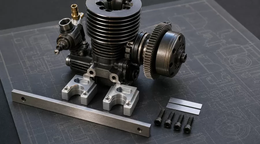
Quick answer: A nitro RC engine should sit on clean, flat, compatible mounting surfaces without being pulled into position by its screws. Dry-fit the engine and mount, confirm that the mounting-lug undersides make even contact, start every fastener by hand, and correct incompatible parts or damaged surfaces before tightening. Use shims only where the exact vehicle or engine instructions permit them. Align the clutch-bell and driven-gear axes, tighten the mount progressively, then recheck the mesh through a full revolution because tightening can move the engine. A flat mount is a reference surface, not a force-fit tool.
Key takeaways: distinguish engine-lug shims from clutch-bell shims; never use mounting screws to bend an engine onto a mismatched mount; record the original hardware order; tighten in stages; verify free rotation after every stage; and stop if the engine rocks, a screw will not start freely, the mount is cracked, or the mesh changes when the chassis is gently loaded.
Why is engine mounting different from gear-mesh diagnosis?
Gear mesh describes how two compatible gears engage. Engine mounting establishes the surfaces and axes that make that engagement possible. If the engine case is twisted across uneven mounts, the mounting screws are side-loaded, or one mount moves while the other stays fixed, a paper-strip mesh check can look acceptable at one point and still change after final tightening.
This guide therefore starts before the clutch bell touches the spur. It focuses on installing the engine without forcing the crankcase and on preserving alignment while the hardware is tightened. For diagnosing worn teeth, bell bearings, clutch shoes, pitch compatibility, runout and repeated spur failure, use the separate nitro RC clutch-bell and spur-gear diagnostic guide. Keeping the jobs separate prevents a damaged bearing or eccentric spur from being mistaken for an engine-mount problem.
What are the four mounting interfaces?
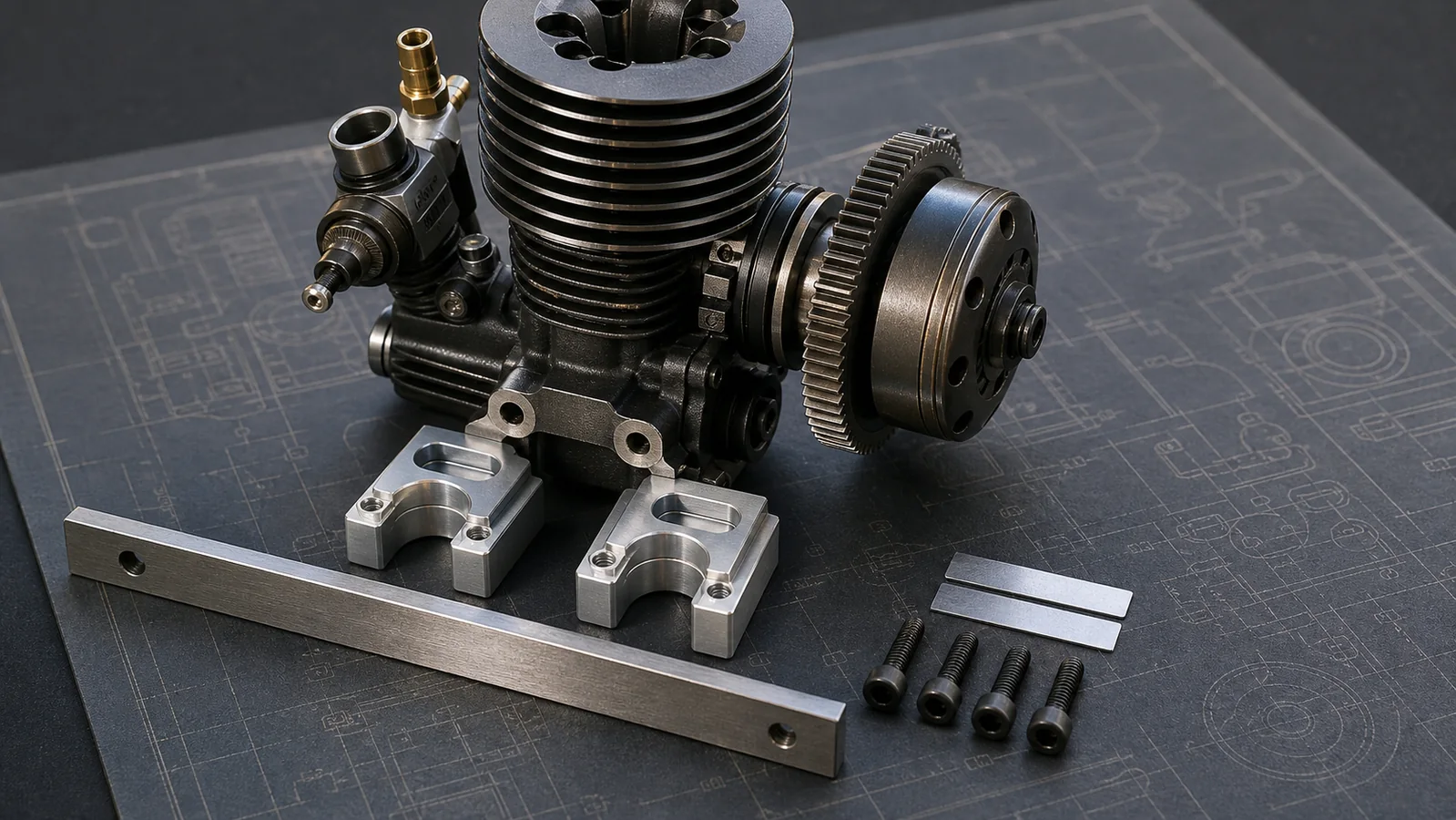
- Engine lugs to upper mounts. Beam-style crankcase lugs are intended to rest on compatible, flat mount surfaces. O.S. engine instructions warn that inaccurate or misaligned mounts can stress and distort the engine, and they specify contact at the lug undersurfaces.
- Upper mounts to chassis or lower mount. Split mounts, monoblock mounts and keyed systems locate the engine differently. Their slots, dowels, shoulders and washers are functional geometry, not interchangeable decoration.
- Mounting screws to threaded holes. A screw should start by hand with the engine already positioned. If tightening the screw is what pulls the engine sideways, the hole pattern, screw length, thread, mount orientation or engine family may be wrong.
- Clutch-bell axis to driven-gear axis. The shafts must remain appropriately aligned while center distance is set. Final mesh is a verification of the installed geometry, not a cure for a rocking or twisted engine.
These interfaces can fail independently. An engine may sit flat but use the wrong clutch-bell offset. A bell may have correct axial play but the mount can shift in its chassis slots. A mesh may feel free before the bottom screws are tightened and bind afterward. Treat each interface as a separate inspection checkpoint.
What should you prepare before removing the engine?
- The exact vehicle manual, exploded view and engine manual.
- Correct drivers, a clean tray, lint-free cloth and a non-marring brush.
- A straight reference edge suitable for the accessible mount faces, plus a bright light.
- The manufacturer-specified paper or card only if the vehicle manual uses that mesh method.
- Approved replacement screws, washers, shims and threadlocking compound only where the manual specifies them.
- A phone or camera to record mount orientation, shim order, washer order, fuel-line routing and linkage position before disassembly.
Do not begin by buying generic shims. First identify the vehicle, engine, crankshaft style, clutch, bell, mount and chassis. Similar-looking .12, .18 or .21 engines can use different lug spacing, mount height, flywheel geometry, bell offset or starter clearance. The RC engine models collection can help with discovery, but the vehicle maker's parts list remains the compatibility authority.
A controlled nitro RC engine mounting workflow
1. Disable the model and freeze the configuration
Stop the engine, close the fuel system as the maker directs, disconnect any electric starter or receiver power, and let the engine, exhaust and clutch cool. Put the chassis on a stable stand. Photograph the installation from above, below and along the clutch-bell axis. Record which fasteners enter the engine lugs and which secure the mount to the chassis.
If the engine was removed because of vibration, a crash or repeated loose hardware, do not assume the old arrangement was correct. Inspect the broader evidence with the model-engine vibration and mount guide before copying a distorted setup.
2. Clean and inspect every reference surface
Remove dirt, cured threadlocker, burrs and trapped debris without removing sound metal from a precision surface. Check the underside of each engine lug, the top of each mount, the mount-to-chassis faces and the chassis slots. Look for raised edges around screw holes, crash marks, fretting, cracks, pulled threads and washers embedded into soft material.
Place the engine on the mounts with no screws installed. It should not rock under light fingertip pressure. A visible gap is evidence to investigate, not permission to clamp harder. Confirm that both mounts face the correct direction and that any keyed features or shoulders are seated. If the engine or mount is visibly damaged, stop and replace or professionally correct the part rather than filing until it fits.
3. Dry-fit the screws without side load
With the engine resting naturally, insert all engine-to-mount screws and turn each several threads by hand. Do not fully tighten one corner. If one screw will not start freely, remove it and determine why. Check thread pitch, screw diameter, screw length, mount orientation and hole alignment. O.S. instructions for some engines explicitly say that holes should be brought into alignment rather than forcing skewed screws; the exact remedy depends on the engine and mount documentation.
A screw that binds before its head reaches the lug can be cross-threaded, bottoming, contaminated or entering at an angle. A screw that starts only after the engine is pushed sideways indicates a geometry conflict. Correct the cause while the parts are unloaded.
4. Establish the engine position before clamping
Install the clutch and bell exactly as the vehicle manual specifies. Confirm that the bell bearings are seated and the bell has the model-specific axial freedom. Team Associated, for example, publishes a 0.2-0.5 mm clutch-bell axial-play range for particular RC8 assemblies; that number is evidence of a model-specific procedure, not a universal target for every nitro RC.
Move the engine or adjustable lower mount through its intended slots until the bell and driven gear have proper face overlap and the shaft axes appear correctly aligned. Do not use mesh tightness to hide poor lateral overlap. Check exhaust, starter, pull-start, air-filter and linkage clearance without allowing those components to pull the engine away from its natural position.
5. Tighten progressively and recheck after every stage
Bring the engine-to-mount screws down in a cross pattern using small, even increments. Then tighten the mount-to-chassis fasteners in the sequence and to the torque procedure specified by the vehicle maker. Keep watching the lug contact and alignment. If a gap opens or the engine rotates as one screw is tightened, stop, loosen the assembly and resolve the cause.
XRAY's XT8 instructions explicitly tell builders to set alignment and mesh, tighten the screws, and then recheck the mesh because the mounts may move. That final sentence is important: a correct loose-fastener position is not proof of a correct clamped position.
6. Set final mesh only after the mount is stable
Follow the exact model's procedure. Traxxas specifies approximately 0.1 mm copy paper for its nitro support method; other makers use different paper, card or feel-based instructions. Rotate the full spur by hand and check several positions. Hold one gear and gently rock the other only as the manual describes. There must be no binding, damaged teeth or visible change in overlap.
If the mesh cannot be correct across the full revolution, do not keep moving the engine back and forth. Inspect spur runout, bell-bearing play, bent shafts, incorrect gears and mount movement using the dedicated gear-mesh troubleshooting workflow.
Where do shims belong?
The word “shim” describes several different parts, and mixing their jobs can create a new fault.
| Shim location | What it may control | What it must not be used to hide |
|---|---|---|
| Clutch-bell or crank pilot | Model-specific axial position or end play | Bad bell bearings, wrong crank hardware or a bent pilot |
| Engine lug to mount | Only a maker-approved height or alignment correction | A warped mount, incompatible lug spacing or debris under one corner |
| Mount to chassis | Only a documented chassis/mount setup | Cracked chassis, raised screw holes or mismatched mount geometry |
| Transmission or differential | Gear-specific axial location according to that assembly manual | Nitro engine-mount misalignment |
Do not place a single loose shim under one engine lug merely because the mesh looks better. That can create a point load and twist the case when the screws are tightened. If a documented setup calls for mounting shims, use the specified part, location and matched arrangement. If documentation is absent, record the shim requirement as UNKNOWN and contact the vehicle or engine manufacturer.
How should the installation be verified?
- Static free-rotation check: with the engine disabled, rotate the complete driven path slowly through at least one full spur revolution. Stop at any tight spot.
- Fastener witness check: verify that every required washer and fastener is present and seated. Apply threadlocker only where specified and only to clean, compatible metal threads.
- Gentle chassis-load check: support and lightly load the chassis as normal handling would, without bending it. Recheck mesh. A large change suggests mount, brace, chassis or center-driveline movement.
- Linkage and clearance check: confirm that throttle/brake linkage returns freely and does not pull the engine. Use the nitro RC throttle-linkage and failsafe guide before running.
- Short controlled heat-cycle check: only after all static checks pass, follow the vehicle manual for a brief, low-load test. Stop for abnormal noise, heat, debris or movement. Let the assembly cool and recheck the fasteners and mesh.
Do not tune the carburetor to cover mechanical drag. If the engine will not idle or restart after a correct mechanical installation, keep those diagnoses separate with the model-engine carburetor tuning guide, the model-engine no-start workflow and the starter-system guide.
Mounting symptom-to-cause table
| Observation | Plausible cause | Next safe check |
|---|---|---|
| Engine rocks before screws are installed | Debris, burr, warped mount, wrong mount orientation or incompatible geometry | Remove the engine and inspect all contact surfaces |
| One screw will not start by hand | Wrong thread, bottoming screw, cross-thread, misaligned hole or shifted engine | Remove the screw and verify hardware and hole alignment |
| Mesh tightens during final tightening | Mount movement, uneven clamping or engine rotation | Loosen, reset in stages and observe which fastener changes the position |
| Face overlap is poor although backlash feels acceptable | Wrong bell offset, shim order, flywheel/collet stack or engine lateral position | Compare the complete clutch stack with the exploded view |
| Mesh changes when chassis is lightly loaded | Chassis flex, loose brace, cracked mount or moving lower mount | Inspect the chassis and mount system before powered testing |
| Fasteners loosen repeatedly | Vibration, damaged threads, wrong hardware or an unresolved moving interface | Stop; inspect vibration sources and repair threads to the maker's procedure |
Limits and safety
- There is no universal shim thickness, screw torque, paper thickness or clutch-bell end-play number for every nitro RC.
- Manufacturer instructions may differ between beam-mount aircraft or helicopter engines and vehicle-specific crankcases. Apply a source only to the interface it actually documents.
- Do not grind an engine crankcase, elongate a chassis slot or substitute fasteners unless the exact manufacturer procedure authorizes it.
- Keep hands, hair, clothing and tools away from the clutch bell, spur, flywheel and starter. Perform alignment work with the engine off and cool.
- Replace cracked mounts, damaged gears and suspect bearings before powered testing. Do not rely on harder gears to absorb misalignment.
Before the first run, inspect the air filter with the nitro RC air-filter maintenance guide. If the engine has been stored, follow the nitro-engine storage and restart procedure rather than forcing a dry or corroded engine.
Frequently asked questions
Should I put shims under a nitro RC engine?
Only if the exact engine or vehicle instructions specify the shim part, location and purpose. A generic shim under one lug can create uneven support and case distortion. First verify mount compatibility, cleanliness, flat contact and hardware alignment.
How do I know whether the engine mount is flat?
Clean the contact surfaces, place the engine on the mounts without screws and check for rocking or visible gaps under good light. Use only non-damaging reference tools appropriate to the accessible surfaces. If the engine rocks or a gap changes as screws are tightened, stop and inspect the parts rather than clamping harder.
Can mounting screws pull the engine into alignment?
No. The engine should already be correctly located before the screws are tightened. Using screws to drag the engine sideways can cross-thread hardware, side-load the screws, shift the mesh or distort the crankcase.
Are clutch-bell shims the same as engine-mount shims?
No. Clutch-bell shims usually control model-specific axial position or end play on the crank pilot. Engine-mount shims, where explicitly approved, alter the support geometry between the engine, mount or chassis. Never exchange their functions.
Why did the gear mesh change after I tightened the engine?
The engine or mount may have moved in its slots, rotated during uneven tightening, settled onto debris or been pulled by misaligned screws. Loosen the assembly, inspect the contact surfaces and repeat the staged tightening procedure. Always recheck the full spur revolution after final tightening.
Should I use threadlocker on engine-mount screws?
Use only the type and locations specified by the vehicle or engine maker, generally on clean compatible metal threads. Threadlocker cannot repair damaged threads, an incompatible mount, uneven contact or ongoing vibration.
Conclusion
A reliable nitro engine installation begins with geometry, not tightening force. Let clean reference surfaces locate the engine, start every fastener without side load, use only documented shims, align the clutch and driven axes, and tighten progressively while watching for movement. Recheck the mesh after final tightening and after gentle chassis loading. If the engine rocks, a screw binds, a mount is cracked or the alignment changes, stop and correct that evidence before applying power.
References
- O.S. Engines - 105HZ-R Instruction Manual: Engine Installation and Mounting-Lug Contact
- Traxxas Support - How Do I Set the Gear Mesh on My Traxxas Model?
- XRAY - XT8 2024 Instruction Manual: Engine Alignment and Post-Tightening Mesh Recheck
- Team Associated - RC8B4.1 Nitro Manual: Clutch-Bell Shimming and Axial Play
- HPI Racing - Maintenance Guide: Fasteners, Bearings and Gear Mesh
- Losi - Speed-NT Owner's Manual: Engine Installation and Gear-Mesh Procedure
Leave a comment