

Quick Answer
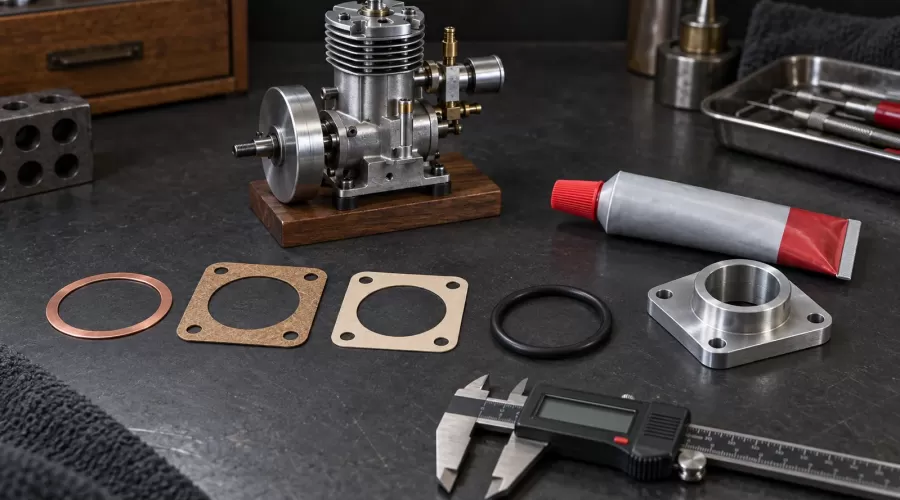
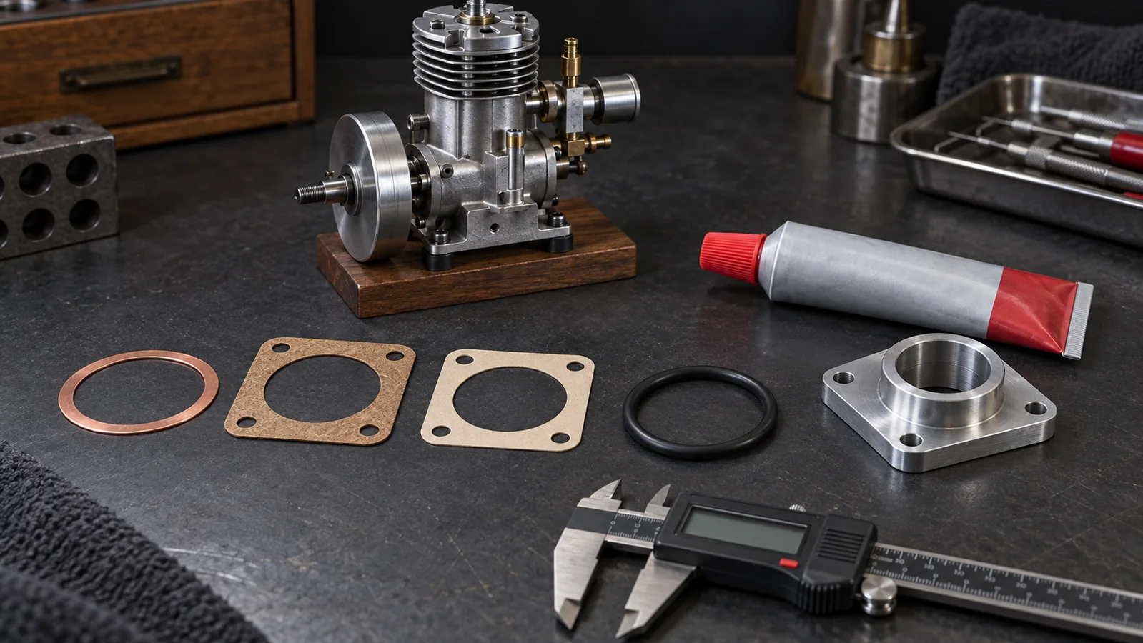
Choose a model-engine gasket or sealant by the joint design, the fluid and temperature exposure, and the exact maker specification - not by color or a generic “high temperature” label. A paper or fiber sheet may fill a designed gap; a copper ring can carry heat and clamp load only in a joint designed for it; an O-ring needs the correct groove and elastomer; an anaerobic flange sealant is intended for close-fitting rigid metal faces; and an RTV silicone is only a candidate where its own data sheet and the engine maker allow it. Never replace a head gasket, fuel-exposed seal or precision spacer with an arbitrary tube of sealant.
The J-F-C decision record separates joint geometry, fluid exposure and curing evidence. Use it before ordering or assembling. It is a documentary framework, not a universal compatibility chart, thickness specification or torque table.
Key takeaways
- The engine drawing or current manual outranks a general compatibility chart.
- Gasket thickness can be part of valve timing, port alignment, gear mesh, compression clearance or shaft location; it is not automatically disposable geometry.
- Fluid resistance is compound-specific. “Rubber,” “silicone,” “fiber” and “RTV” are families, not complete specifications.
- An O-ring is an engineered seal with a groove, squeeze and surface requirement; it is not a round substitute for a flat gasket.
- RTV cure, bead size and squeeze-out matter. Excess material can enter a passage even when the outside looks neat.
- A leak test can verify the assembled joint under stated conditions, but it does not prove long-term chemical compatibility.
Start with the joint, not the material shelf
Before choosing anything, identify what the joint was designed to do. Photograph the stopped, cool engine before disassembly and mark the two mating parts. Record every port that crosses the joint, every dowel, fastener and locating feature, and the original gasket or seal position. The model-engine tools and assembly checklist explains the clean-bench controls that prevent a small sealing job from becoming a contamination problem.
A joint between two close, rigid, machined metal faces behaves differently from a stamped cover with a deliberate gasket gap. A circular groove designed for an O-ring behaves differently from either. A combustion joint sees alternating pressure and heat; a crankcase cover may mainly retain oil; an intake flange may be sensitive to a tiny air leak; and a steam joint adds water, steam and repeated thermal cycling. The same material name cannot safely answer all of those conditions.
Thickness is often functional. Replacing a specified sheet with liquid sealant can move a cover inward, change end clearance, alter gear or cam alignment, disturb port registration or raise compression. Adding a thicker homemade gasket can produce the opposite errors and reduce fastener engagement. Do not “improve” thickness unless the drawing or maker gives an approved dimension and tolerance.
The evidence hierarchy
- Exact engine manual, drawing or service instruction. This governs material, thickness, part number, preparation, torque, sequence and cure.
- Exact gasket or sealant technical data sheet. Confirm substrate, joint type, gap, temperature, fluid exposure and application procedure.
- Supplier application confirmation. Use it when the published sheet does not cover the exact fluid or duty.
- General handbooks and compatibility tables. Use them to screen questions, never to overrule the first three levels.
- Old appearance or forum memory. Treat these only as clues. Color and texture do not identify a compound.
The FAA's active AC 20-77B emphasizes manufacturer maintenance manuals. A miniature engine is not an aircraft engine, but the transferable discipline is sound: the correct service instruction must govern the exact assembly.
Paper, fiber, copper and O-rings: what each choice can and cannot prove
| Seal type | Typical designed role | Evidence required | Common misuse |
|---|---|---|---|
| Paper or cellulose sheet | Specified low-gap cover, carburetor or crankcase joint | Exact grade, thickness, fluid and temperature approval | Cutting from unknown packaging or changing a precision stack height |
| Compressed fiber sheet | Conforming flat gasket where a sheet is designed into the joint | Binder/fiber identity, thickness, clamp load, fluid and temperature data | Assuming every tan sheet is fuel-safe or reusable |
| Copper ring or washer | Model-specific combustion, exhaust or plug sealing geometry | Specified alloy/condition, dimensions, surface condition and reuse rule | Adding copper to a joint not designed for it or annealing without authorization |
| Elastomer O-ring | Static or dynamic groove seal | Exact compound, size, groove, squeeze, lubrication and fluid exposure | Choosing only by diameter or stretching into a flat-gasket role |
| Anaerobic flange sealant | Close-fitting rigid metal flanges where approved | Substrates, maximum gap, cure conditions, fluid and disassembly method | Filling a large gap or replacing a thickness-setting gasket |
| RTV silicone | Maker-approved flexible formed-in-place gasket or dressing | Exact product restriction, bead, skin/cure time, fluid and temperature exposure | Using “high temp” as gasoline, head-gasket or universal approval |
Sheet gaskets
Paper and fiber sheets are engineered materials, not interchangeable craft paper. Their fibers, binders, density and coatings affect compressibility, creep, fluid resistance and removal. The Garlock gasketing technical manual illustrates why chemical service and material style must be matched. Its industrial ratings are useful screening evidence, but they do not authorize a Garlock sheet, a pressure limit or a thickness for a model engine.
Trace a replacement only after the original part identity and thickness are verified. Punch clean bolt and passage holes; ragged fibers can hold a flange off its seat or enter a passage. Keep sealant out of a dry paper joint unless the service instruction calls for a dressing. If the old gasket tears, remove residue with a method that does not gouge aluminum, round an edge or fill an oilway with abrasive debris.
Copper sealing parts
Copper can tolerate heat and conform under controlled clamp load, which is why designed copper washers or rings appear in some plug, exhaust and combustion joints. That does not make copper sheet a universal head gasket. Required thickness, hardness, surface finish and annealing practice are joint-specific. A used ring that looks flat may already have work-hardened, deformed or imprinted beyond its reuse limit.
The FAA maintenance handbook discusses copper and other gasket materials as distinct service choices. Use that as evidence that material and location matter, not as permission to transfer aircraft dimensions to a miniature engine. Follow the model maker's replace/reuse instruction. Do not anneal, lap or coat a copper part unless the exact service method says to do so.
O-rings
An O-ring seals by controlled deformation in a correctly sized groove. Cross-section, inside diameter, stretch, squeeze, gland fill, clearance, surface finish and motion all matter. The Parker O-Ring Handbook provides compound-compatibility ratings and design fundamentals. It also shows why “fuel-safe rubber” is incomplete: ratings vary by elastomer and fluid, and design limits vary between static and dynamic service.
Do not select an O-ring merely because it fits over a spigot. An oversized cross-section can prevent faces from closing; an undersized ring may not squeeze; excessive stretch can thin the section; twisting can create a spiral failure. Use the specified assembly lubricant only when compatible with both the compound and process. Replace a cut, flattened, hardened, swollen or unidentified ring rather than hiding the defect with sealant.
Fuel, oil, steam and heat are separate questions
Fluid compatibility must cover the exact fuel or lubricant blend and the real exposure mode. A seal that briefly contacts a splash may behave differently under continuous immersion. Methanol-based glow fuel, nitromethane blends, gasoline with ethanol, mineral oil, synthetic oil, steam condensate and exhaust residue create different environments. Temperature, pressure, flexing, concentration and exposure time can change the result.
The model-engine fuel-tubing compatibility guide applies the same exact-formulation rule to hoses. For gasoline and ethanol storage decisions, use the separate E10/E15 fuel guide. Neither page proves a gasket compound, but together they help define the fluid that the gasket supplier must evaluate.
Temperature ratings also need context. A data sheet's upper temperature value does not prove combustion-pressure sealing, fuel resistance, gap capability or repeated thermal-cycle life. Elring describes its Dirko silicone range and links product technical sheets; the useful lesson is to read the exact sheet. Do not turn one range-level temperature claim into approval for a head, exhaust, crankcase or carburetor joint.
RTV versus anaerobic flange sealant
RTV silicone cures through a moisture-driven process and remains elastomeric. Anaerobic flange sealant cures between close-fitting metal faces where air is excluded and the material is suited to the substrates. They are different chemistries for different joint designs. Neither is a generic upgrade over a specified sheet gasket.
Permatex Ultra Black's own instructions provide a decisive example: the manufacturer says it is not recommended for head gaskets or parts in contact with gasoline. That restriction matters more than the words “oil resistant,” “OEM” or “high flexibility.” It also demonstrates why reading only the front label is inadequate.
Henkel describes LOCTITE 518 as a semi-flexible anaerobic product for close-fitting rigid aluminum, iron or steel flanges, with a stated gap capability. That is a product-specific application envelope. It does not authorize filling a large warped gap, coating an O-ring groove, replacing a spacer gasket or sealing an unknown fuel passage.
Why bead size and cure matter
More sealant is not more sealing. Excess squeezed inward can detach or obstruct a fuel, oil, cooling or pressure passage. Excess outside the joint only proves that some material escaped; it does not prove full contact inside. Apply the exact bead or film, encircle holes as instructed, assemble within the stated working time, tighten by the specified sequence and allow the full cure before adding fluid or pressure.
Surface preparation is equally product-specific. Elring's Dirko HT technical sheet calls for clean, dry, oil-free sealing surfaces. Do not substitute an aggressive scraper or solvent that attacks coating, plastic or elastomer. Protect open passages during cleaning and remove every protective plug before assembly.
The J-F-C selection and assembly workflow
- Make the engine safe. Stop, cool and secure it. Isolate ignition, glow power, fuel and starting equipment. Vent or drain only by the maker's procedure.
- Identify the joint. Record the engine model, two mating parts, ports, locating features, fastener pattern and whether thickness sets a mechanical clearance.
- Freeze the original evidence. Photograph the intact joint and old part, measure only where the manual permits, and retain labels or part numbers. Do not copy damage as design.
- Define fluid and heat exposure. Name the exact fuel, oil, coolant, steam or exhaust environment; note immersion versus splash, static versus moving service and known temperature limits.
- Select by specification. Match the manual to an exact sheet grade, copper part, O-ring compound/size or sealant product. Treat every unresolved condition as UNKNOWN.
- Prepare without changing geometry. Remove residue and burrs using the approved method. Check flatness and damage only against published limits.
- Install the specified amount. Keep holes and passages clear. Use the approved lubricant, dressing, bead, torque, sequence and cure time. Do not add a second material “for insurance.”
- Inspect the closure. Confirm the faces seated, dowels engaged, shafts rotate as required and no material entered a passage. Stop if the joint will not close normally.
- Run the approved static test. Use only the maker's pressure, fluid and duration. A high-pressure improvised air test can eject parts or drive fluid into unintended spaces.
- Return to service gradually. Run secured and attended, checking leakage, temperature, sound and control response. Record the part, batch, date and observations.
When a rebuild also includes a piston or ring, the piston-ring end-gap guide keeps that clearance separate from gasket thickness. For valves, use the valve-seat leak guide. These measurements interact in symptoms, but each requires its own evidence.
Do not use sealant to hide a diagnosis
A difficult start, weak compression or unstable mixture does not prove a failed gasket. Leakage may be at a valve, piston ring, carburetor base, backplate, plug washer, fuel line or test connection. Start with the compression and leak-down guide and the controlled air-leak guide before disassembly.
Evidence at a joint should be repeatable: visible wetting, bubbles under an approved low-pressure method, a documented pressure decay, soot or oil tracks, or a dimensional defect confirmed against limits. Surface staining alone may be historical. Do not smear RTV around the outside of an assembled joint and call the leak repaired; that can hide evidence without restoring clamp or sealing geometry.
If the engine overheated, identify the cause before replacing a gasket. The model-engine overheating guide separates mixture, cooling, lubrication, timing and mechanical drag. A new gasket cannot safely compensate for a continuing thermal fault.
Safety and evidence limits
Wear eye protection, provide ventilation and follow every product safety data sheet. Sealants and cleaners can irritate skin or eyes and may release vapors. Fuel is flammable. Keep flames, hot surfaces, sparks and smoking materials away; never use oxygen to test a fuel or oil system. Dispose of contaminated wipes and uncured chemicals according to local rules.
This guide does not specify a universal gasket material, thickness, torque, bead size, cure time, O-ring compound, pressure or temperature. It does not authorize asbestos-containing legacy material, homemade annealing, resurfacing, head machining or operation with a known leak. If an old gasket cannot be identified or the joint is damaged, stop and obtain the drawing, replacement part or qualified support.
When comparing model engine kits, ask whether the maker supplies drawings, replacement gaskets, O-ring sizes and approved sealants. A documented service path is a meaningful purchasing advantage. It is safer and more useful than an unsupported promise that a kit can be sealed with common workshop materials.
Frequently asked questions
Can I replace a paper gasket with RTV?
Only if the exact engine instruction authorizes it. Paper thickness may set clearance or alignment, and RTV has different gap, cure and squeeze-out behavior.
Is high-temperature RTV safe for gasoline?
Not automatically. Temperature and fuel resistance are separate properties. Permatex Ultra Black, for example, explicitly excludes parts in contact with gasoline and head-gasket use.
Can I use LOCTITE 518 instead of any flat gasket?
No. Henkel describes 518 for close-fitting rigid metal flanges within its stated envelope. It is not a substitute for a spacing gasket, flexible cover, O-ring or unidentified fuel joint.
How do I identify an unknown O-ring?
Color is not enough. Record dimensions and location, then obtain the engine part number or compound specification. Replace an unidentified fuel- or heat-exposed ring only with approved evidence.
Should a copper head gasket be annealed before reuse?
Only if the exact maker's service procedure permits reuse and specifies the method. Alloy, condition, thickness and surface treatment vary, and uncontrolled heating can create a false sense of repair.
Can I cut a gasket from cereal-box cardboard?
No general approval exists. Unknown paper has unknown thickness, binder, compressibility, temperature and fluid resistance. Use the specified gasket material and part.
How much RTV should squeeze out?
Use the product and engine instructions, not an appearance target. Visible squeeze-out does not prove the inner bead is safe; excessive material can obstruct a passage.
Does passing a leak test prove the material will last?
No. A static test verifies the assembled joint under that test's conditions. It does not establish long-term chemical resistance, thermal cycling or service life.
Conclusion
The safest gasket decision begins with geometry, not a tube or sheet on the bench. Preserve the designed thickness, name the exact fluid and temperature exposure, verify the precise material or product, and follow its preparation and cure instructions. The J-F-C record makes those decisions reviewable and keeps a convenient sealant from quietly changing a precision engine joint.
References
- Permatex: Ultra Black RTV product instructions and restrictions
- Henkel: LOCTITE 518 rigid-flange sealant specification
- Parker: O-Ring Handbook ORD 5700
- FAA: Aviation Maintenance Technician Handbook - General
- FAA: AC 20-77B, Use of Manufacturers' Maintenance Manuals
- Elring: Dirko sealing compounds
- Elring: Dirko HT technical data sheet
- Garlock: Gasketing Technical Manual
Leave a comment