

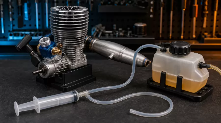
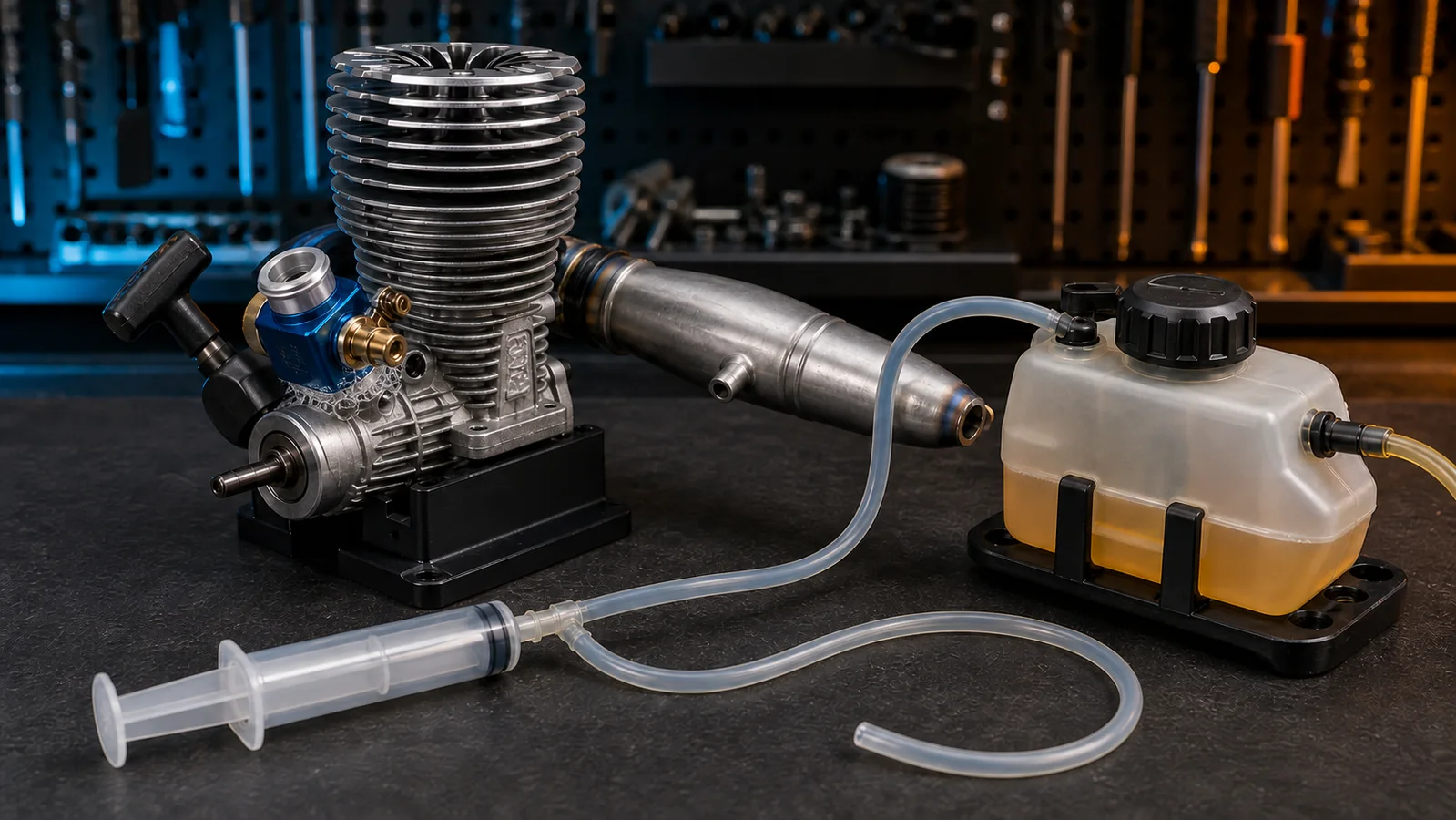
 Quick answer: Diagnose a suspected nitro RC engine air leak by separating three systems: throttle control, tank/exhaust pressure, and the engine's intake/crankcase path. Check servo travel and carburetor return first. Then inspect the tank cap, clunk, fuel line, pressure line and exhaust seal. Only if the exact engine or vehicle maker permits a static leak check should you use a low-force hand syringe or bulb, block the specified openings, apply a removable soap solution to one joint at a time, and stop as soon as a leak location is identified. Never use mouth pressure, shop compressed air, flame, or a running engine. Bubbles near a front bearing are evidence to interpret against that engine's construction—not an automatic replacement verdict.
Key takeaways: a high idle is not proof of an air leak; a pressure line can fail without the engine case leaking; throttle movement must be diagnosed independently; needle settings cannot repair a damaged seal; and a test that lacks a known pressure limit or blocking procedure can create more uncertainty than it removes. A leak test is a localization tool, not permission to keep leaning the needles.
What does “air leak” mean on a nitro RC engine?
A glow-powered nitro RC engine meters fuel through pressure differences. Exhaust pressure is commonly routed to the fuel tank, helping move fuel toward the carburetor; the carburetor then meters air and fuel into the engine. The HPI Nitro Star manual explains the pressure-line role, while the O.S. SPEED R21GT manual shows that carburetor O-rings, retainers and exhaust seals are deliberate parts of that system.
An “air leak” is therefore not one generic fault. It can mean unmetered air entering at the carburetor base or another engine interface, lost exhaust pressure before it reaches the tank, a tank or fuel-line fault that interrupts delivery, or a test setup that lets air escape through a path the design never intended to seal statically. The remedy depends on which circuit failed.
This distinction matters because leaning a needle may temporarily change the sound while increasing heat and reducing lubrication. The Losi operation manual warns that excessively lean operation can overheat a nitro engine and reduce lubrication. If the mixture changes without a matching needle change, stop tuning and find the cause.
Which symptoms suggest a leak—and which do not prove one?
Possible leak symptoms include an idle that hangs after a throttle blip, tune settings that change as the fuel level falls, a mixture that becomes unexpectedly lean, visible fuel-line bubbles, difficult priming, inconsistent restart behavior, or an engine that responds to tuning at first and then drifts. None is conclusive alone.
High or stuck throttle opening: first inspect the transmitter command, servo, linkage, return spring and carburetor barrel. Crankcase pressure should not be treated as the explanation for a mechanically open barrel. Follow the separate throttle-linkage, endpoints and failsafe guide .
Lean only near an empty tank: tank height, clunk position, pressure-line routing, cap seal or exhaust-pressure delivery may be more likely than an engine-case leak. Use the fuel tank, clunk and vent diagnostic guide .
Hard starting: glow-plug condition, flooding, fuel age, starter direction and compression can mimic leakage. Start with the model-engine no-start workflow and the glow-plug troubleshooting guide .
Hot running: a leak is one possible route to a lean condition, but airflow, load, gearing, fuel and needle position also matter. Stop sustained running and use the overheating and cooling guide .
Dirt around the carburetor: contamination can damage metering parts or seals. Confirm that the filter is intact and correctly oiled using the nitro air-filter maintenance guide .
The three-circuit isolation method
1. Throttle-control circuit
With the engine off and receiver powered only when safe, observe the carburetor barrel through full brake, neutral and full-throttle commands. The barrel should return repeatably to the model-specific idle opening without the linkage pushing against a hard stop. Switch the radio off only as the radio maker directs and verify the failsafe action. Disconnecting the linkage for a manual barrel check can isolate binding, but record the original geometry and restore it exactly.
2. Tank and exhaust-pressure circuit
Trace the pressure tube from the tuned pipe or muffler to the tank and the fuel tube from the clunk outlet to the carburetor. Look for split ends, hardened tube, loose nipples, sharp bends, contact with hot parts and a cap that does not close uniformly. The Kyosho MP11 documentation treats pressure-tube connection and routing as required installation details, not optional tidy-up.
Test the tank circuit separately from the engine. Empty and clean the system as its maker specifies, isolate it from the carburetor, then use only the maker-approved hand-pressure method. A tank that will not hold the specified test condition points to the cap, nipple, tube, clunk or tank body. It does not prove a crankcase leak.
3. Intake and crankcase circuit
Only after the first two circuits pass should the engine itself be considered. Review the exact manual before blocking any opening. The permitted crank position, carburetor position, exhaust-port closure and pressure source differ by design. If the maker publishes no static test, do not invent a pressure value; inspect seals and fasteners, or ask the manufacturer or a qualified engine service technician.
Tools, preparation and non-negotiable safety limits
The exact engine and vehicle manuals, exploded views and seal part numbers.
A clean hand syringe or low-force bulb with compatible soft tubing—only if the maker permits it.
A dilute removable soap solution applied externally with a small brush or swab.
Plugs or caps specified for the openings being isolated; improvised hard plugs can damage ports.
Eye protection, nitrile gloves, a ventilated bench, absorbent pads and a tray for removed parts.
A timer or camera to record where bubbles begin, rather than increasing pressure to make them dramatic.
The engine must be stopped, cool, secured and away from ignition sources. Remove fuel or handle it exactly as the fuel and vehicle maker require. Never blow through a fuel or pressure line by mouth: model fuel is poisonous and its residues should not contact the mouth or eyes. Never use a compressor, aerosol propellant or combustion gas. Never spray liquid into a running engine, and never turn the engine with an opening blocked unless the maker's procedure explicitly requires it.
Step-by-step nitro RC engine air-leak diagnosis
Step 1: Freeze the tune and record the symptom
Do not begin by turning every needle. Record fuel type, ambient conditions, tank level, warm-up state, high-speed and low-speed needle positions, idle gap, when the symptom appears and whether braking changes it. Photograph all hose routing. A repeatable symptom gives the test a target; an undocumented tune creates a moving baseline.
Step 2: Prove that the throttle closes
With the engine off, verify transmitter trim, servo endpoints, horn security, linkage freedom and return behavior. If the barrel stays open when the linkage is disconnected, service the carburetor as the engine maker directs. If it closes manually but not under radio control, correct the control system before leak testing.
Step 3: Inspect before pressurizing
Check the carburetor pinch bolt or retainer, base O-ring, backplate screws, starter housing, fuel nipples, exhaust coupler, exhaust gasket and pressure nipple. Do not automatically tighten everything. The O.S. manual identifies an O-ring at the carburetor interface and cautions against excessive retainer force; overtightening can distort parts or damage threads instead of improving the seal.
Also inspect the filter neck. A split rubber boot or loose clamp can admit unfiltered air above the carburetor. The symptom may resemble a lower seal leak while leaving the crankcase test unchanged.
Step 4: Isolate and check the pressure/fuel system
Disconnect it from the engine so the result cannot be blamed on two systems at once. Follow the tank maker's approved closure and hand-pressure procedure. Look for bubbles at the cap seal and fittings and for a clunk line that has split inside the tank. The Associated Electrics .50 engine manual lists both carburetor-area air leakage and a lost muffler-pressure connection among relevant troubleshooting checks.
Step 5: Perform a maker-approved engine test at minimum force
Set the crankshaft and carburetor exactly as the manual specifies.
Block only the specified openings with non-damaging caps.
Attach the hand syringe or bulb before applying soap solution.
Apply just enough slow hand force to observe the specified response. Do not chase a universal pressure number.
Brush a thin film onto one joint at a time: carburetor base, backplate seam, starter housing seam and any maker-identified interface.
Release the test immediately after locating a repeatable bubble source. Clean and dry every tested surface.
Large bubbles at a carburetor-base O-ring, repeated at the same low-force condition, are useful localization evidence. Random foam caused by brushing, bubbles from a loose test plug, or a result that appears only after force is increased are not equivalent.
Step 6: Repair the confirmed interface—not the symptom
Use the correct seal, gasket, fastener order and torque procedure. Do not substitute household sealant, thread tape or excess threadlocker in a fuel-exposed intake path unless the manufacturer specifically authorizes that material. Replace hardened or cut O-rings. Correct warped, cracked or stripped parts rather than clamping them harder.
Why is the front bearing easy to misdiagnose?
The front crankshaft support is visually prominent and close to the carburetor on many engines, so test fluid can migrate there and make the first visible bubble look decisive. But front-bearing constructions differ: shields, seals, lubrication paths, shaft clearances and intended static sealing behavior are not universal. A static test also does not reproduce the same temperature, rotation and pressure pattern as a running engine.
Therefore, front-area bubbles are a reason to verify the test setup, clean the area and consult the exact engine documentation. Corroborating evidence can include roughness, radial play outside the maker's allowance, contamination, repeated leakage at the same controlled condition or a maker-specific service test. A single bubble with unknown pressure is not enough to order a bearing.
Before condemning the bearing, confirm that the bubble did not travel from the carburetor base, pinch-bolt recess, fuel nipple or test plug. Apply solution sparingly and test one joint at a time. If bearing replacement requires crankshaft or sleeve removal, use the maker's service procedure or a qualified rebuilder.
Evidence matrix: what should happen next?
What should you do after a confirmed repair?
Repeat the same isolated test at the same low-force condition. Reconnect hoses using the original routing, reinstall the filter, confirm the throttle returns and perform a range/failsafe check. Start from the maker's conservative baseline needle settings—not from the lean settings used while compensating for the fault. The model-engine carburetor tuning guide explains how to warm the engine and adjust one circuit at a time.
For the first run, use a safe stand or open area, keep observers clear and stop if the idle hangs, temperature rises rapidly, fuel flow becomes discontinuous or the model does not respond correctly to brake/failsafe commands. Recheck the repaired joint after cooling. If dirt or corrosion was found, review storage and after-run practice before the next long layup.
Choosing a replacement engine or compatible parts should follow the vehicle's dimensions, crankshaft, mount, clutch and exhaust requirements. The RC engine models collection is a discovery starting point, not a substitute for the vehicle maker's compatibility list.
Frequently asked questions
Can I pressure-test a nitro engine by blowing into the fuel line?
No. Do not put a fuel, pressure or exhaust line in your mouth. Residual model fuel is hazardous. Use only a clean, low-force hand tool and the exact maker-approved method.
What pressure should I use for a nitro RC engine leak test?
There is no safe universal value for all engines, tanks and test configurations. Use the exact manufacturer's procedure. If none is published, do not substitute shop-air pressure or an internet number; use inspection or qualified service.
Does a hanging idle always mean the engine has an air leak?
No. A lean mixture can hang, but so can a binding carburetor, incorrect idle stop, tight linkage, servo command, clutch drag or changing load. Prove that the throttle closes and isolate the fuel-pressure circuit before testing the engine.
Do bubbles at the front bearing prove the bearing is bad?
No. They are evidence, not a universal verdict. The result depends on bearing construction, crank position, applied force, fluid placement and the maker's intended test. Seek corroborating mechanical evidence and model-specific guidance.
Can I seal a leak by adding silicone around the carburetor?
Not as a default repair. An incompatible sealant can enter the intake, resist fuel poorly, hide damage or prevent correct seating. Replace the specified O-ring or gasket and correct the retaining hardware according to the manual.
Should I retune immediately after replacing a seal?
Return to the maker's conservative baseline first. Confirm fuel flow, throttle return and safe temperature, then tune one circuit at a time after warm-up. Settings used to compensate for a leak may be dangerously wrong once the leak is repaired.
Conclusion
A reliable nitro RC engine air-leak test begins with separation, not pressure. Verify the throttle mechanism, isolate the tank/exhaust-pressure system, inspect known seal interfaces and test the engine only with a maker-approved low-force setup. Interpret bubbles by location, repeatability and engine design. That process turns a vague “lean” symptom into a repairable finding without sacrificing lubrication, damaging seals or replacing a front bearing on weak evidence.
Related EnginesDIY Guides
Model-engine carburetor tuning guide
Fuel tank, clunk and vent guide
Throttle linkage, endpoints and failsafe guide
Model-engine no-start troubleshooting
Nitro RC air-filter maintenance
Authoritative References
O.S. Engines SPEED R21GT instruction manual
HPI Racing Nitro Star F5.9/F4.6 engine manual
Associated Electrics .50 engine manual
Losi nitro vehicle operation manual
Kyosho Inferno MP11 official documentation
Leave a comment