

By EnginesDIY Editorial Team | Published and reviewed September 24, 2026
Quick Answer
A shaft coupling does not excuse poor alignment. Before joining a miniature engine to a generator, pump or display load, identify each shaft and coupling, mount both machines without distorting their bases, and check parallel offset, angular error, the specified axial gap and rotating runout as separate conditions. A flexible coupling may accommodate a defined amount of misalignment, but its rating belongs to that exact part at its intended speed, torque and environment. If a model or coupling drawing is missing, do not invent a permissible gap, shim or tightening torque.
The O-A-R record separates offset, angle, axial clearance and runout before a coupling is chosen. O is the difference between shaft centerlines where the coupling operates; A is their angular relationship; axial clearance records hub position and permitted shaft-end movement; R asks whether a shaft or hub rotates concentrically in the first place. This is an editorial inspection worksheet, not a replacement for maker instructions or a certification of safety.
Key takeaways
- Identify the engine, driven device, shaft diameters, shaft ends and actual coupling before adjustment. Matching outside appearance does not prove matching bores or safe speed.
- Parallel offset, angular difference, axial position and runout have different causes. A single straightedge check cannot settle all four.
- Check that every mounting foot seats on a stable base without being pulled flat by a screw. Soft foot can change the alignment as fasteners are tightened.
- Use the coupling maker's combined limits, not one maximum from each column added together. Lovejoy explicitly warns against operating at both angular and parallel maxima simultaneously.
- Perform inspection with ignition and electrical power isolated, hot parts cooled and the coupling stationary. Never place a gauge or hand beside a running exposed drive.
- Document a before/after condition and escalate unknown tolerances, damaged shafts, cracks, repeated heating or critical rotating loads.
What exactly is being aligned?
A model engine may rotate freely on the bench and still become noisy when a generator is attached. That change does not prove the generator is faulty, and it does not prove the engine needs more power. The attachment can add load, constrain an end of the crankshaft, shift a bracket, or reveal a hub that was not concentric. Begin by separating the geometry from the resulting symptom. The detailed Lovejoy coupling handbook defines angular and parallel offset separately and treats axial travel as another design input.
Parallel or radial offset
The two centerlines point in the same direction but do not coincide at the coupling. On a tiny bench rig, unequal foot height, a skewed adapter plate or a generator bracket sitting on debris can produce this condition. A flexible element may bend during each revolution to take up that displacement. The fact that it can be assembled is not proof that the cyclic load is within its rating. Record the location and direction of the difference rather than using an arbitrary “looks straight” verdict.
Angular misalignment
The centerlines point in slightly different directions. Opposite sides of appropriately referenced coupling faces then have different gaps. A straightedge may reveal a gross tilt, but the part geometry and reference surfaces matter. The Fluke alignment method comparison distinguishes visual and straightedge inspection from feeler gauges, dial indicators and laser measurement. Its industrial examples illustrate why a quick screening tool cannot certify a precise tolerance on an unrelated miniature coupling.
Axial gap and permitted movement
The shafts also need the correct lengthwise relationship. A hub forced hard against a case, two shaft tips touching inside a coupling, or an insert compressed beyond its intended position can push on bearings even when the side view looks straight. Thermal expansion or shaft end float may change the gap in service. The Huco misalignment guide notes that temperature and installation tolerances can alter alignment after the first setup. Do not copy a gap dimension from a photograph; use the exact component drawing.
Runout is not the same as shaft-centerline alignment
A bent shaft, eccentric hub, burr, dirty bore or damaged bearing can make a visible edge wobble as it turns. Trying to move the generator until that wandering edge appears centered may actually misalign two sound shaft centerlines. Check the maker-approved reference surface and method before concluding the mounts are wrong. Our flywheel taper and key diagnosis deals with a different but related shaft-to-hub problem; the bearing clearance and endplay guide explains why dragging or heating can have a bearing cause rather than an alignment-only cause.
A careful O-A-R bench inspection
1. Isolate energy and identify the exact assembly
Shut down, disconnect starter/battery power and disable ignition in the way the equipment manual specifies. Allow cylinders, exhaust parts, heaters and bearings to cool. If the machine is steam-powered, follow its pressure-isolation procedure; this article is not a depressurization instruction. Secure loose clothing and tools before any later maker-approved test. Photograph the base, both hubs, keys, inserts and shaft positions as found. Label the driver and driven unit. Do not separate a safety-critical propeller or high-speed drivetrain on the basis of this general article.
Record the model and revision for the engine, generator or driven device and coupling. Record the drawing or manual revision too. Look for shaft diameter, bore type, keyway, clamping method, permissible torque and RPM, rated misalignment in each direction, hub insertion and axial spacing. If the two shafts use different diameters or one is tapered, there is no reason to assume a generic straight-bore coupling fits. “All-metal construction” or a similar product listing phrase cannot substitute for dimensional evidence.
2. Check the mounting foundation before the coupling
With the coupling not imposing a side load, confirm the approved mounting feet and brackets contact their base as intended. A foot that rocks until a screw is tightened may indicate soft foot, a missing spacer or an uneven base. Tightening it harder can distort the driven housing. Verify each fastener, washer and spacer against the kit documentation. Our engine mounting and shimming guide covers mount geometry in greater depth, while the screw-length guide explains why a fastener can feel tight without clamping a mount.
Do not correct a rocking foot by inserting a random shim and calling the alignment fixed. First determine why the intended stack does not seat. If the manual specifies shims, use the specified material, area and sequence. If the base or bracket is visibly cracked, bent or insecure, replace or repair it under the maker's instructions before any alignment attempt.
3. Record O and A using appropriate references
Begin with a powered-off visual screen for obvious offset, skew and inconsistent face gap. A sound straightedge across suitable machined hub surfaces may reveal a large error; it does not establish a numerical tolerance. If the assembly warrants more accuracy and the maker provides an indicator setup, document where the gauge contacts the hub, the shaft rotation method, reference position and readings. The SKF coupling instructions distinguish dial checks for angular and parallel alignment. They do not supply universal numbers for all model couplings.
At this stage, write “unknown” if the reference surface is damaged or the appropriate tolerance is absent. The industrial Rexnord shaft-alignment manual distinguishes measured indicator travel from the actual parallel offset between hub centers. Therefore, do not report a raw dial swing as a centerline offset without the exact geometry and calculation prescribed for the setup. A misleading number is worse than an honest unknown.
4. Record axial clearance and shaft condition
Check hub position, shaft engagement and the specified separation of ends while the assembly is stationary. Note whether a set screw, clamp or key can contact a shoulder or bearing seal. Check that the coupling insert, if any, is the right component and installed in its intended orientation. Do not grind a shaft, file a key, shorten a hub or force the shafts together to manufacture clearance. A loose coupling can transmit intermittent torque and misleading vibration; an overtight one can add thrust or bind a bearing.
Check the individual shafts and hubs for visible damage. When the manufacturer permits a runout check, use its specified surface, support and tool. If a hub edge wobbles while the shaft reference does not, investigate the hub fit instead of moving the whole machine. If the shaft itself shows suspected bending or a bearing is rough, stop. The optical RPM guide can help interpret a later non-contact speed check, but speed measurements do not certify alignment.
5. Adjust, document and re-check without a running hazard
Only after identifying the actual error should a qualified person move the adjustable component within the maker's permitted mounting range. Change one variable at a time and remeasure after tightening, because the act of tightening can shift a small bracket. Preserve a simple record: “as found,” correction, “as left,” reference surface, tool and remaining unknowns. If one correction worsens another dimension, the problem may be combined offset plus angle or a poor base rather than insufficient effort. Do not trade a large angular error for a large radial error and call the net appearance acceptable.
If the manufacturer instructs a post-warm-up inspection, perform it only under its guarded and isolated procedure. Huco's industrial explanation notes that thermal change can matter, but no reader should put a hand near a hot or spinning miniature mechanism to imitate a factory test. Cooling, shutdown and isolation are prerequisites to touching the drive. A repeated change between cold and cooled-after-run measurements is evidence to report, not permission to alter an unknown design target.
Choosing a coupling after measuring the problem
Coupling selection starts with the duty and geometry, not the material color. Establish shaft bores and attachment method, rated torque and peak load, operating speed, environmental temperature, expected angular and parallel error, axial movement, available length and acceptable backlash. Lovejoy explicitly cautions that operating simultaneously at separate maximum misalignment ratings is inappropriate. A single “flexible” label cannot tell you the combined operating envelope.
A rigid coupling can be compact and torsionally direct, but requires the particular assembly to meet its much stricter alignment requirements. A jaw-style elastomer coupling, a beam coupling and an Oldham-type coupling accommodate errors by different mechanisms. None is universally best: insert material, torsional stiffness, speed, temperature, end float and service access all matter. If a product listing lacks the coupling maker's ratings or exact bore, request those facts instead of treating the photograph as a specification. A high-speed flywheel or a model aircraft powertrain needs its own engineered guarding and approval.
For a heat-driven classroom display, begin with the Stirling generator model category and the generator power and load-testing guide. Those pages help decide whether the desired outcome is visible motion, an LED indicator or a documented electrical load. They do not verify that a particular external coupling or motor can be added. For broader engine demonstrations, browse model-engine kits and check each model's provided shaft interface before ordering parts.
Symptom-to-evidence table
| Observation | Possible explanations | Next safe evidence | Avoid |
|---|---|---|---|
| Runs freely uncoupled, stiff when connected | Offset, axial compression, driven load or bearing problem | Isolated hand-turn only if manual permits; inspect gap, base and independent shafts | Increasing throttle to force rotation |
| Insert wears unevenly or repeatedly splits | Combined misalignment, overload, wrong insert or hub fit | Exact insert identification, O/A record and rated duty | Installing another identical insert without diagnosis |
| Noise appears after mounting screws are tightened | Soft foot, bracket shift, distorted housing or contact | As-found versus after-tightening readings and mount seating | Backing out a critical screw while running |
| Hub edge wobbles every revolution | Eccentric hub, burr, bent shaft or bearing fault | Runout at maker-approved shaft and hub references | Moving the other machine until the wobble looks centered |
| Speed falls with an electrical load | Normal added demand, overload or mechanical loss | Permitted no-load/load measurements plus alignment record | Assuming all voltage drop is an alignment failure |
| Gap changes after heating and cooling | Thermal movement, loose mount or bearing movement | Maker-approved cold/recheck comparison after safe isolation | Touching or adjusting an operating exposed coupling |
Symptoms guide investigation but do not make a diagnosis alone. Vibration can arise from imbalance, fuel misfire, loose mounting, gear mesh or a damaged bearing. The model-engine vibration guide is the companion path when the drive is noisy even without the added coupling. If product documentation differs, use the model number rather than assuming a generic recommendation transfers.
Limits, evidence quality and safety
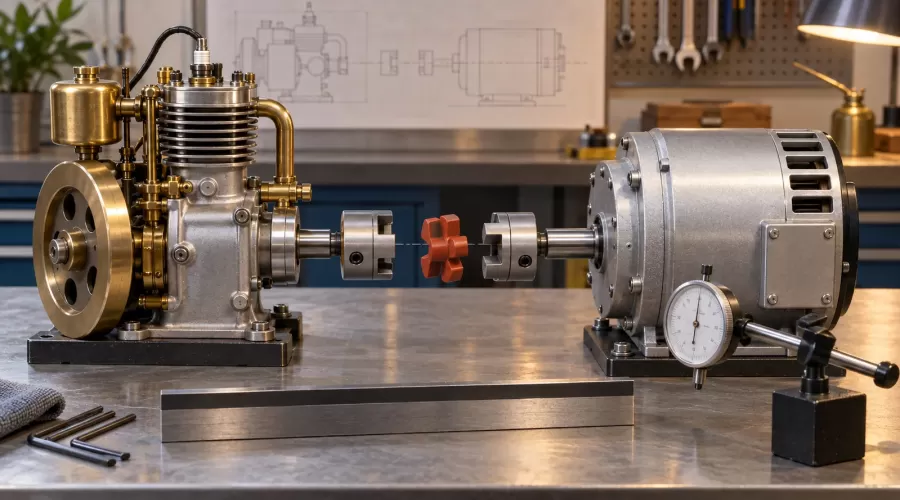
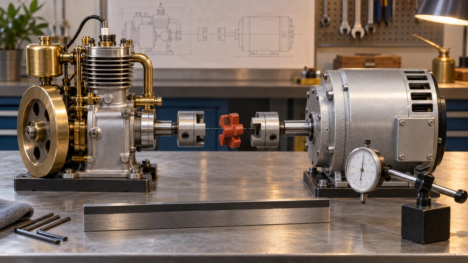
The five primary references below are written for their authors' coupling or industrial measurement contexts. They establish the categories of misalignment and why measurement matters. They do not establish a safe tolerance, RPM, torque or gap for every tabletop engine. No engine/generator pair in this article was physically tested. The featured image is conceptual. If the actual coupling's documentation is unavailable, the acceptance criterion remains unknown; leave the assembly unpowered until it is resolved.
Keep exposed shafts guarded according to the maker's instructions. Avoid loose sleeves, hair, cords and instrumentation near rotating parts. Do not work near a hot burner, hot exhaust, pressurized steam or energized electrical terminals. Any suspected cracked hub, loose key, damaged bearing, recurring hot spot or contact with a guard is a stop condition. A stationary unloaded hand-turn, where explicitly permitted, is only an early screen and cannot establish safety at operating speed. A cooling period and power isolation come before each physical inspection.
For purchasing, ask for the driven load's actual requirement, documented shaft features, coupling part number and replacement insert availability. Product pages are starting points, not proof of compatibility. If the assembly is intended to fly, propel a vehicle, run at high speed or drive an electrical load beyond a learning indicator, obtain the appropriate engineering and manufacturer approval; this general workshop guide is not a design authorization.
Frequently asked questions
Can a flexible coupling fix badly misaligned shafts?
No. Flexibility is rated for particular kinds and amounts of error at specified duty. It reduces neither the need to measure nor the need to bring the base into the maker's accepted range. Combined errors may be more restrictive than either individual maximum.
Is a straightedge enough to align a miniature engine and generator?
It can catch a gross fault on suitable reference surfaces. It cannot alone establish angular, axial and running concentricity to an unknown tolerance. Use the exact maker-approved measurement method when precision matters.
What if the coupling spins but the generator housing heats up?
Stop and isolate it. Heating can reflect electrical load, bearing friction, poor ventilation or mechanical misalignment. Check the separate component documentation and evidence before attributing it to one cause. Do not increase engine power to compensate.
Does a wobbling coupling mean the shafts are misaligned?
Not necessarily. A hub may be eccentric or damaged, or the shaft/bearing may have runout. Compare approved shaft and hub reference surfaces before moving a mounting plate.
Can I choose an Oldham, jaw or beam coupling by shaft diameter alone?
No. Bore fit is only one gate. Torque, speed, error direction, axial travel, stiffness, insert material, environment and space also determine whether a named part is suitable.
Should I recheck alignment after the first run?
Follow the exact model and coupling instructions. Where they require a post-run check, shut down, cool and isolate before touching it. Do not use an industrial manual's timetable or numerical tolerances as universal miniature-engine settings.
Conclusion
The most useful first question is not “Which flexible coupling should I buy?” but “Which relationship between these two shafts is wrong, and how do I know?” An O-A-R record turns an ambiguous noise or drag complaint into a documented set of geometry, mounting and shaft-condition checks. Fix the base and identify the actual coupling limits before changing parts. When evidence is missing, preserve the unknown rather than converting a guess into an operating instruction.
References and review limits
- Lovejoy, The Lovejoy Coupling Handbook — definitions and combined-rating caution.
- Huco, Coupling Misalignment — assembly and temperature-related displacement.
- Fluke, How to Check Pump Coupling Alignment — screening and measurement methods.
- SKF, Couplings manual — manufacturer-specific angular and parallel checks.
- Rexnord, Shaft Alignment manual — axial, angular and offset definitions.
Reviewed by EnginesDIY Editorial Team on September 24, 2026. Recent keyword demand and a complete survey of search results are not established. The article is educational and does not claim field testing, product compatibility, a universal acceptance tolerance or a Google ranking outcome.
Leave a comment