

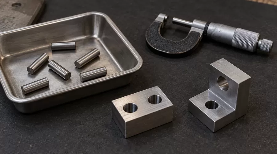
Quick answer: Identify a model-engine locating pin by its exact part reference, geometry, material specification and intended fit in each mating component. A nominal diameter is not a complete replacement specification. If the drawing, hole condition or installation method is unknown, stop before pressing, hammering, drilling or using the assembly screws to pull the parts together.
The P-H-F record separates pin identity, hole evidence and fit authority before a model-engine locating joint is assembled.
Key takeaways
- A locating pin and a screw can serve different jobs; do not assume one substitutes for the other.
- Solid, slotted, coiled, tapered and pull-out pins are distinct families.
- Record the fit separately for each mating hole, not just for the whole joint.
- Keep uncertain measurements and unknown tolerances visible in your notes.
- Unexpected resistance is a reason to investigate, not permission to increase force.
Why a small pin deserves a separate decision
A loose cylindrical part in a model-engine kit can look unimportant beside the crankcase, crankshaft or cylinder head. Its appearance alone says little about the relationship it establishes. Depending on the actual design, a pin may locate two components, retain another part or perform a different specified function. This article concerns identification and evidence before assembly. It does not claim that every model engine contains the same pin arrangement, and it does not supply an installation procedure for an unidentified model.
The practical mistake is to reduce the decision to whether a pin seems to enter a hole. An easy entry could be correct for one interface and wrong for another. Resistance could reflect a specified interference, contamination, misalignment, damage or a mismatched component. A casual trial cannot distinguish those possibilities reliably. Instead, separate what you see from what the documentation authorizes. This makes a useful question for a supplier and avoids turning an uncertain identification into permanent damage.
Start with the model, version and assembly step. Keep the pin in its labeled packet when possible. If several similar parts were mixed, photograph their original locations and sort them without testing each one in the most convenient hole. A part that seems to fit is not automatically the part specified there. The same principle applies to other small components; our shim, washer and spacer identification guide treats function and location separately from superficial similarity.
Separate pin families before comparing sizes
Manufacturer catalogs show why the word pin is too broad for a replacement order. Unbrako lists dowel, slotted and pull-out pin categories, while Carr Lane organizes multiple alignment-pin designs. These examples establish a taxonomy, not a compatibility recommendation for your engine. A smooth solid cylinder should not be replaced by a spring pin simply because both have a similar nominal diameter.
Look for a seam, slot, coil, taper, shoulder or threaded extraction feature without modifying the part. Some features are obvious in a clear side photograph; others require the exact drawing. Do not polish away a finish, enlarge a slot or shorten an end to make a candidate resemble the original. Those changes can remove useful identity evidence and alter a component whose dimensions or material requirements you have not established.
The Elesa+Ganter DIN 6325 catalog page illustrates a named standardized dowel family. A standard designation helps narrow an inquiry, but its appearance in a general catalog does not prove your kit uses that standard. Keep the manufacturer's part number ahead of your visual guess. If the instructions call only for a pin and contain no dimensions, ask for the corresponding illustrated parts list rather than importing specifications from an unrelated industrial product.
Bossard's dowel-pin catalog is another primary classification reference. A catalog category is not evidence of model-specific installation suitability; use the actual component designation rather than matching only its general name.
Build a P-H-F evidence record
P-H-F is an editorial checklist for this guide, not an industry standard. P means the pin itself, H means the mating holes and F means the documented fit and installation authority. Write three short entries before any irreversible action. The purpose is not paperwork for its own sake: an empty field shows exactly why the next step is unsafe to assume. It also helps another person review your evidence without needing to recreate the whole disassembly.
| Record | What to preserve | What does not prove it | Stop condition |
|---|---|---|---|
| P: pin | Model/version, part number, family, diameter/length specification and source drawing | A similar photograph or one rounded reading | Mixed parts or conflicting designation |
| H: holes | Component identity, hole location, accessible condition and drawing reference | The pin entering a different hole | Burr, damage, debris or uncertain location |
| F: fit | Specified relationship for each interface and approved assembly/removal method | Generic advice that pins should be tight | No applicable fit or method evidence |
For P, distinguish the supplier's nominal size from your observation. A measurement can support identification, but it is not a tolerance certificate. Record the instrument, units and where the reading was taken. If the surface is damaged, mark that limitation. Do not silently round a measured value to the nearest available catalog size and then describe the selected item as an exact match.
For H, identify both components rather than naming the joint vaguely. A case half and a cover may have different intended relationships to the same pin. A blind hole also raises different inspection and removal questions from an accessible through hole. Record what can be seen without probing with a cutting tool. A photograph of a clean entrance does not establish the condition of the entire bore.
For F, quote the applicable drawing reference or instruction step in your private service notes, and distinguish that authority from advice gathered online. A general article about industrial alignment pins can explain why fit matters, but it cannot approve a press operation on a thin miniature casting. If the documents disagree, preserve both versions and ask the manufacturer to resolve the conflict.
Nominal diameter is not the fit
SPIROL's alignment dowels and bushings catalog discusses hole tolerances, engagement and centerline position as interrelated design considerations. The relevant lesson for a model builder is narrow: the diameter label by itself is incomplete. This guide deliberately does not reproduce a general fit chart as an engine-specific hole-sizing instruction. Host material, geometry, pin design and the designer's intended service relationship all require applicable evidence.
A drawing can specify that the pin remains associated with one component while the other component is removable. Do not assume that arrangement unless your drawing actually shows it. Record the two interfaces independently: pin to component A, then pin to component B. If one field is missing, the presence of a complete specification for the other does not fill the gap.
Measurement resolution is another limitation. A display with several decimal places does not guarantee that a workshop reading can settle a close fit question. Handling, cleanliness, alignment and instrument condition matter. Consult our caliper versus micrometer guide for selecting a measurement task, then keep its uncertainty separate from the replacement decision. A tool choice is not permission to determine a machining allowance from one reading.
When a supplier offers two pins with the same nominal size but different tolerance descriptions, do not choose the cheaper one and hope the joint accommodates it. Ask which exact specification matches the original part and why. The answer should refer to your model and interface, not merely to the fact that both products are called dowel pins. If that evidence cannot be obtained, the replacement remains unapproved.
Resistance is a symptom, not an installation instruction
When parts fail to approach their documented assembly position, pause and preserve the situation. Do not immediately draw them together with screws. A screw can generate force while concealing whether the locating features are aligned. The appearance of progress under tightening is not evidence that the pin, hole or orientation was correct. Follow the model's approved sequence and stop when its stated checks cannot be met.
Make a non-destructive review first: are the two component identities correct, is the orientation supported by the manual, and have the correct pins remained with the correct assembly? Review whether another part or visible debris obstructs the mating surfaces. These are observation questions, not instructions to scrape, ream or grind. If cleaning is needed, use the manufacturer's approved method and protect other components from contamination.
Unbrako's engineering guide includes installation warnings for its hardened dowel products. Those warnings demonstrate why hammering advice should not be generalized across pin families. They do not establish the material or method for an EnginesDIY item. If the engine manufacturer supplies no acceptable installation method, obtain one rather than treating an industrial catalog as a substitute service manual.
Keep eye protection and the manufacturer's safety requirements in the plan for any authorized work. Disconnect relevant power and allow the assembly to reach a safe condition before inspection. Do not work on a running or hot engine. An unexpectedly stuck pin, visibly damaged housing or unexplained movement changes the task from routine identification to a repair assessment. Continuing with greater force is not a diagnosis.
Blind holes and removal features need their own evidence
A pin with an internal extraction thread is not necessarily a screw fastener. Its feature may exist for an approved removal method. Before using it, establish the pin identity and the specified tool or thread. An apparently compatible screw is not adequate proof. Our diameter and pitch identification guide helps structure that inquiry without assuming a particular thread size.
Do not drill an unidentified hardened pin, weld to it, drive it through a blind hole or heat a miniature housing on the basis of a generic tutorial. Those are separate repair operations with potential consequences for surfaces, adjacent parts and the housing itself. Their safety and suitability require the exact assembly, material information and manufacturer-approved method. This article intentionally provides no extraction-force or temperature recipe.
If a pin is already loose after disassembly, do not turn that observation into permission for an oversized replacement. The original condition, previous repair history and hole geometry may be unknown. Record the looseness and ask whether the manufacturer calls for inspection, a named service part or component replacement. A larger catalog diameter is not automatically a valid repair.
A replacement inquiry that can actually be answered
Send a compact evidence packet: engine model and version, the assembly location, instruction step, original part reference, clear photographs and measurement notes. Identify whether the part is missing, damaged or merely uncertain. Explain what has not been changed. This separates a request for identification from a request for permission to repair and makes it less likely that a supplier answers the wrong question.
Ask for the exact pin designation, intended fit in each mating component, installed position and approved installation or removal method. Also ask whether the replacement relates to a particular production revision. Do not assume a later revision part fits an earlier housing. A written answer that lacks the assembly identity should remain provisional until the supplier confirms it applies to your version.
For buyers considering model-engine kits, check the selected configuration's actual contents and documentation. This category link is a shopping context, not a claim that a particular kit includes a particular locating pin. Before ordering a replacement, confirm the exact part independently; this guide does not certify compatibility, inventory or delivery for any pin.
Three scenarios and the appropriate decision
A pin looks identical but its specification is incomplete. Preserve the original, record the candidate's published details and compare the missing fields. The correct outcome is a focused supplier question, not a trial press. Visual similarity is useful for screening but cannot establish tolerance, material or revision compatibility. Even if the candidate passes through a loose sample hole, that observation does not approve it for the real joint.
One component accepts the pin and the other resists. Check the documented interface relationship and orientation before interpreting resistance. The two holes need not serve identical roles, but unequal behavior alone does not prove that the intended arrangement has been achieved. Stop if either interface lacks applicable evidence. Do not swap pins between multiple locations until one combination seems to work.
The assembly closes only when screws are tightened. Do not use that as a fit test. Review the manual's sequence and all locating features. The separate screw length and bottoming guide explains another reason a tightening observation can mislead. The locating joint and the screw joint both need their own checks rather than one being used to conceal uncertainty in the other.
Frequently asked questions
Is every smooth cylinder a dowel pin?
No. Confirm the part reference and assembly role. Similar geometry can belong to different component families, and a visual inspection does not establish material, tolerance or intended use.
Can I replace a solid locating pin with a spring pin?
Not without explicit applicable design approval. Different pin families have different behavior and requirements. A shared nominal diameter is not enough to approve substitution.
Should both mating holes hold the pin tightly?
Use the exact drawing or manufacturer instructions. Record the intended relationship for each interface separately; do not assume both are identical or infer a correct fit from resistance alone.
Can a caliper prove a replacement is correct?
A reading can support identification but cannot replace the required tolerance, material and revision evidence. Record the instrument and uncertainty; do not convert a rounded observation into an exact specification.
Can I hammer a pin that will not enter?
Do not improvise an installation method. Unexpected resistance needs investigation, and hardened pin products can carry specific warnings. Obtain the method approved for the exact engine assembly.
Does a threaded end mean the pin screws into the engine?
Not necessarily. It may be an extraction feature. Confirm the component design and applicable tool or thread before using it, and do not assume the feature's function from appearance.
What should I do if the locating hole is damaged?
Stop assembly and seek an exact-model repair assessment. Do not enlarge the hole, select an oversized pin or use retaining chemicals as an undocumented workaround. Preserve the condition and replacement history.
Conclusion and limits
Identify first, record each interface and obtain fit authority before assembly. The P-H-F record provides a simple way to keep evidence and uncertainty visible. It is not a substitute for a model-specific drawing, a tolerance inspection or qualified repair. For planning the wider bench setup, see the kit tools and assembly checklist. No pressure, force, temperature, hole-sizing or compatibility specification is established by this article.
Sources are primary manufacturer and component-provider materials used to distinguish terminology and evidence requirements. They are not service instructions for an unidentified miniature engine. No physical test, supplier approval, stock confirmation, ranking improvement or purchase outcome is claimed.
Leave a comment