

Quick answer
Identify the screw's drive family, confirm the required driver size from the exact assembly documentation, and check clean, straight engagement before applying turning force. A bit entering a recess does not prove that it fits correctly. Keep thread diameter, head shape and drive size as separate facts. If the recess is damaged, the tool rocks, or the documentation conflicts with the fastener, stop and resolve the identity instead of trying progressively more force.
This guide concerns choosing and checking a hand-tool interface on a stationary model. It does not supply universal torque values, approve a substitute screw, or describe extraction from a running, hot or energized engine. A motorized demonstration kit and a combustion engine can both contain small fasteners, but their assembly requirements are not interchangeable. The exact manufacturer instructions remain the authority.
Key takeaways
- A cross-shaped recess is not a sufficient specification: establish the documented profile and size.
- Socket size is not thread diameter. Metric and inch hex tools require separate identification.
- Good access means the tip can engage correctly, not simply that the handle clears the model.
- A worn bit can imitate a wrong-size bit. Inspect both sides of the interface.
- Fit identifies a suitable tool candidate; it does not determine tightening torque.
Three identities, not one small screw
A builder may call a part a small silver screw, then order a driver based on a photograph. That description leaves several different interfaces unresolved. The thread joins the screw to its mating material. The head bears on a component or washer. The drive recess receives the tool. Knowing one interface does not completely identify the other two, and a product photograph may show only the outside of the head.
For example, a cylindrical head does not establish the size of its internal socket. A countersunk exterior does not tell you whether the recess is slotted, cross-shaped or lobed. Likewise, a measured shank diameter cannot safely be converted into a driver designation without a corresponding fastener specification. Record the manufacturer part number and assembly location before treating any apparent relationship as a standard rule.
Our thread diameter and pitch identification guide addresses the thread interface. The present article deliberately addresses the tool interface instead. Use both records when a screw must be replaced, but do not use driver fit to approve thread length, pitch, material, strength or bearing geometry. The separate screw length and thread engagement guide explains why a seemingly compatible replacement can still bottom out.
What the manufacturer sources establish
Wera's bit categories distinguish Phillips, Pozidriv, slotted, hex socket, TORX and TORX PLUS, including separate security variants. That catalogue supports keeping profiles distinct; it is not a list of tools approved for any particular model engine. The Phillips Screw Company's Pozidriv page identifies Pozidriv as a defined drive system. Its advertised performance benefits should not be read as permission to exceed the model manufacturer's tightening instructions.
PB Swiss Tools' precision slotted screwdriver set emphasizes appropriately sized tips. Wiha's screw-profile overview distinguishes familiar slotted and cross profiles from newer drive families and stresses a matching tool. Bondhus' tool descriptions include particular ball-end designs for angled access. These are five independent primary tool or drive-system sources, not five independent tests of an EnginesDIY product. Their catalogue claims remain specific to their tools.
The workflow below is an editorial synthesis: separate profile, designation and engagement evidence, then stop when they disagree. It does not reproduce a standards drawing. Exact dimensions, permissible angle, torque and wear limits require the specification for the actual fastener and tool. We have not bench-tested the illustrated items, measured reader engines, or verified a universal driver set.
The P-D-E record
The P-D-E record separates profile, driver designation and engagement evidence before a model-engine screw is turned. Write one entry per distinct fastener group rather than assuming every similar-looking head in the box uses the same tool. Include an assembly location or diagram reference so a later builder can trace the observation back to the original joint.
| Field | Evidence to capture | What it does not establish |
|---|---|---|
| Profile | Exact manual designation and a clear view of the clean recess | Torque, thread size or replacement suitability |
| Driver designation | Tool marking, size system and corresponding fastener specification | Condition of a worn tool or damaged screw |
| Engagement | Straight seating, clearance, intact contact surfaces and no obvious mismatch | A numerical clearance tolerance or safe extra leverage |
| Stop condition | Conflicting designation, rocking, obstructed access or distorted recess | A reason to force another profile into the head |
Photographs help preserve this record, but they should include enough context to identify location. A very close photograph without scale or documentation can exaggerate similarity. Keep the unmodified original image, the manual edition and the tool marking together. If a supplier answers a question, save the reply against the specific model and version rather than extending it to an entire brand.
Recognizing profile families without overclaiming
Start by describing what is visible: a single straight slot, a cross, a six-sided socket or a lobed recess. Treat that description as a preliminary sorting step. Confirm the proper family from the manual or fastener documentation. A dirty or damaged recess can lose the features that would otherwise distinguish it. Do not label it confidently merely because one familiar driver can enter it.
Phillips and Pozidriv are separate documented categories. A cross outline alone is therefore not enough to authorize substitution. Extra surface lines can be clues, but markings, wear and manufacturing details can complicate a photograph. Match the stated designation rather than relying on a single visual shortcut. If the instructions identify only a cross-head screw, ask for the actual profile and size before tackling a tight or delicate joint.
A six-sided socket calls for identifying the specified hex tool, including whether the size is metric or inch. A nearby size from a different system may appear plausible without providing the intended contact. Do not adopt a near match as a workaround. Similarly, keep TORX, TORX PLUS and security variants distinct. A central obstruction or unfamiliar shape is a reason to consult the specification, not to modify a tool or head.
Some older or specialized cross-recess systems require additional identification. This article does not provide a universal test for JIS or other legacy geometries, and we do not infer them from country of manufacture. If the manufacturer calls out a specific driver standard, preserve that requirement. Generic marketplace labels and similarity to another engine are weaker evidence than the matching assembly documentation.
Checking a driver without beginning disassembly
Make the assembly safe according to its instructions: stop motion, allow hot parts to cool, and isolate the relevant power or ignition system. Follow model-specific fuel handling requirements rather than a generic draining procedure. Support the model so inspecting the screw does not put your other hand behind a moving tip or load a fragile mounting bracket.
Use suitable lighting and magnification to inspect the recess. Loose contamination can obscure shape or keep a tool from reaching its intended position. Use only a cleaning method permitted for the assembly and keep debris out of bearings, gears and openings. Do not scrape a profile into a different shape, flood a sensitive assembly with solvent, or regard cleaning as a reason to resume force on a distorted head.
Inspect the bit separately. Look for rounded contact surfaces, a chipped edge, contamination or a tip that has been modified. Compare its markings with the documented requirement. A shiny finish, premium handle or new package is not evidence that the particular tip is appropriate. If a tip has been ground or shortened, its original marking may no longer describe its actual geometry.
Bring the confirmed tip to the recess in line with the screw axis and check that surrounding parts allow the intended engagement. This is a seating inspection, not a loosening test. Stop if it only catches at the mouth, rocks conspicuously, rests on debris, or requires tilting to reach. There is no universal numerical wobble limit in this guide. Ambiguous engagement means the identity record is incomplete.
Access, ball ends and extensions
A short driver may clear a bracket where a long one cannot, but clearance is only one part of the decision. You also need a controlled approach to the screw and a support arrangement that does not bend the surrounding model. Moving the handle sideways to get around an obstruction can change how the tip contacts the recess. If the assembly instructions require removing a cover for access, do not invent a shortcut solely to avoid that step.
Ball ends are designed to address some angled-access situations, but their specifications are tool-specific. A published angle for one Bondhus product does not establish the permissible angle or tightening capability of every ball-end key. Nor does angled insertion establish that the model's joint can be safely tightened that way. Follow the exact tool and fastener requirements, and use a straight-end approach where the relevant instructions require it.
Extensions, universal joints and interchangeable holders add interfaces. Confirm that the bit is retained correctly and that the holder can pass the surrounding features without lifting the tip. A long extension is not a reason to add leverage. A power driver is not a substitute for identifying the profile and checking the prescribed tightening method. Small model parts may be damaged before an operator recognizes a mismatch.
Fit, torque and replacement are separate decisions
Once a driver fits, the next decision is still governed by the assembly instructions. Torque depends on the specified joint and conditions, not simply on the drive shape. Do not copy a torque from a larger engine, another screw of similar diameter or a tool advertisement. Where a setting is required, confirm the units, tool range and procedure with the manufacturer before proceeding.
Likewise, a replacement screw with a convenient drive is not automatically acceptable. Changing the head may alter bearing contact, access or clearance. A different length may bottom out or interfere with moving parts. Material and strength requirements remain unresolved by a good driver fit. Our damaged-thread decision guide concerns the threaded joint; it should not be confused with a damaged drive recess.
Do not assume every loose screw needs additional tightening. It may be an adjustment, a set screw with a specified sequence, or part of an assembly that is meant to move. Before turning anything, identify its function and the correct maintenance action. When the function is uncertain, a photograph and exact part reference are more useful than applying a generic rule about snugness.
Three practical scenarios
Scenario one: the supplied key enters but feels loose. Leave the screw stationary. Check the exact size designation, tool markings, metric or inch system, contamination and tip condition. A supplied tool is useful evidence but not conclusive if the packet is mixed or the tool is worn. Ask the supplier to reconcile the particular screw and key if the discrepancy remains. Do not move to a larger tool and force it into the socket.
Scenario two: a cross-head screw resists while its neighbors moved. Do not infer that the resistant screw just needs more pressure. It may use another profile, have a damaged recess, serve a different function or require a different procedure. Document the location and head before the visible detail is lost. Preserve the remaining intact fasteners and seek the model-specific instruction for that joint.
Scenario three: a driver fits loose screws on the bench but not the installed screw. Compare documentation before assuming they are identical. Check whether access, recess damage or trapped debris changes engagement. A loose spare may belong to another step. Keep removed fasteners grouped by their original positions; the shim, washer and spacer identification guide helps keep adjacent hardware from becoming an anonymous pile.
Buying tools with a bounded specification
Build a list from the exact kit's assembly requirements, then choose tools that cover those requirements. Specify profile, size, size system, reach and any required tightening procedure. Count repeated requirements once; do not buy a large set solely because it contains many pieces. Conversely, a small set is incomplete if it omits one documented profile used in the assembly. Use the broader bench setup and assembly checklist for organization and staged inspection, while keeping this drive-specific record separate.
For broader project selection, browse model engine kits and obtain the exact version's documentation before planning tools. This category link does not imply that every listed kit uses the same screws. Our caliper and micrometer comparison can help with separate dimensional questions, but neither instrument by itself identifies a drive standard from an unclear recess.
A useful support question includes the model, version, manual page, fastener location, clear photograph and available tool marking. Ask which profile and size are specified and whether the observed screw matches the parts list. Avoid asking only which screwdriver fits this engine. A precise question makes it easier to distinguish an assembly mismatch from a tool-shopping issue.
Limits and safety
Stop before the head loses recognizable geometry. This guide excludes drilling, cutting, hammering, heating, adhesive tricks and extraction procedures. Those methods can introduce debris, heat or load into a delicate assembly and require a separate model-specific assessment. Do not work on live electrical equipment or operating engines. Wear appropriate protection and follow both the model and tool instructions.
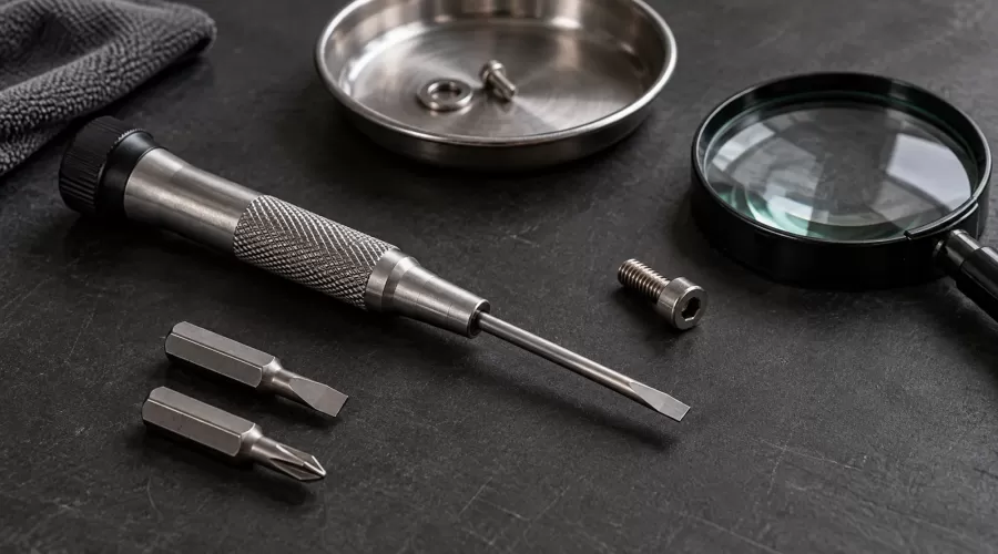
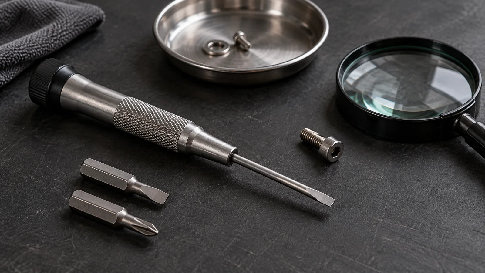
Neither the conceptual image nor the examples establish compatibility with a named engine. Catalogue descriptions are manufacturer claims about particular tools; they are not independent evidence that a model's fasteners tolerate the advertised force or angle. When specifications are missing, record the missing information explicitly and leave the joint unchanged until a responsible source resolves it.
Frequently asked questions
Does a bit entering the recess prove it is the right size?
No. Entry alone does not verify the profile, size system, contact surfaces or condition. Confirm the documented designation and inspect straight engagement without applying loosening force.
Can I use screw thread diameter to choose a hex key?
Not by itself. Thread diameter and socket size are separate specifications. Use the exact fastener drawing, parts list or manufacturer instruction for the driver requirement.
Are Phillips and Pozidriv interchangeable?
They are distinct drive categories. Do not authorize substitution merely because both appear cross-shaped; follow the stated profile and size for the actual fastener.
Is a ball-end key suitable for final tightening?
That depends on the particular tool and joint instructions. Angled access capability is not a universal torque approval. Do not extrapolate one manufacturer's product rating to another key.
Should I replace a screw with one having a more convenient drive?
Only with verified approval for the replacement specification. Driver convenience does not resolve head bearing geometry, thread, length, material, strength or interference.
What should I do when the recess is already rounded?
Stop the fit trial and preserve photographs and the part reference. Treat extraction or replacement as a separate model-specific repair decision rather than increasing force.
Does this guide provide torque settings for my engine?
No. Obtain the specified value, units and procedure for the exact joint from the matching manufacturer documentation. Correct driver fit does not determine tightening torque.
Conclusion
A careful driver choice begins before any screw turns. Separate the profile from the thread and head, confirm the driver designation, and inspect engagement in the actual access conditions. The P-D-E record gives you a traceable stop point when those facts disagree. That is more useful than an unverified tool recommendation and safer than discovering a mismatch after the recess is damaged.
References and evidence boundaries
The linked Wera, Phillips Screw Company, PB Swiss Tools, Wiha and Bondhus pages are primary descriptions of tool families or specific products. They support the distinctions described above, not model-engine compatibility or universal torque settings. Accessed October 13, 2026. The examples and P-D-E worksheet are original editorial reasoning, not reported bench tests.
Leave a comment