

By EnginesDIY Editorial Team | Published and reviewed October 1, 2026
Quick Answer
Oil mist at a model four-stroke crankcase breather is not automatically a fault, and a dry exterior is not automatically proof of a healthy breather. First identify the exact engine and its oil-return design. Some engines have an external nipple that intentionally discharges waste oil; others route it back inside. Then record whether the discharge is stable for that model or has changed suddenly, and inspect only the accessible hose, outlet and neighboring parts permitted by the manufacturer. Stop and seek model-specific help if a tube is kinked, a seal begins leaking, oil output changes sharply, or the engine runs abnormally.
The V-E-N-T record separates visible discharge, engine design, neighboring faults and the next safe test. It prevents a common mistake: treating a fuel-tank vent, exhaust outlet, four-stroke crankcase breather and internal oil return as interchangeable tubes. The method is observational, not a replacement for a service manual. No engine was run, weighed or dismantled for this article, and there is no universal acceptable number of drops per minute.
Key takeaways
- Locate the exact model's lubrication path before calling an oily nipple a leak.
- SAITO documents external breather discharge on one engine, while O.S. documents internal oil return on another: both designs exist.
- A kink or restriction can change crankcase pressure; cross-class sources establish the mechanism, not a hobby-engine threshold.
- Compare the present pattern against a known baseline under the maker's permitted operating conditions.
- Do not cap a breather, connect it to a fuel line, copy another model's routing, or run through a new seal leak.
- If the manual or baseline is missing, record observations and ask the manufacturer before making changes.
Why a four-stroke model may have oil at a breather
A four-stroke engine is defined by its intake, compression, power and exhaust events; that label alone says little about where its lubricant goes. Model engines vary in fuel, oil supply, crankcase design, valve-gear path and whether excess oil leaves by a visible port. The broader model-engine lubrication guide helps identify the oil circuit before choosing a lubricant. Here the narrower question is what a particular crankcase breathing path is doing and how to react when its discharge changes.
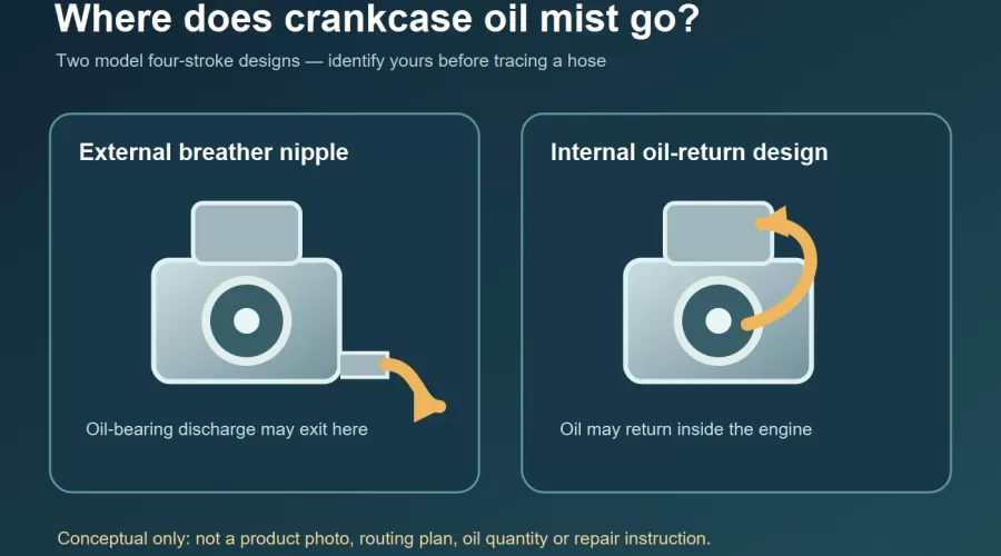
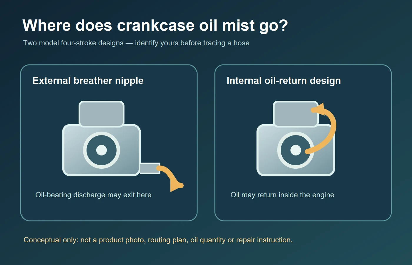
On the SAITO FA-200R3 manual, oil contained in the fuel reaches the crankcase, lubricates internal moving parts, and waste oil is discharged from a nipple at the lower crankcase. SAITO instructs a silicone tube to that nipple and specifies where to secure its other end for that engine. This is evidence that visible oil at the outlet can be an intended result of a specific total-loss-style arrangement. It is not permission to copy the tube material, destination or installation onto a different model. Check the revision and installation instructions for your exact engine.
A useful counterexample is the O.S. FSα-56 product documentation. O.S. describes removing the conventional crankcase breather nipple and recirculating excess crankcase oil through an internal route. An owner of that design would not find the same external waste-oil tube to inspect. This does not mean that an FSα-56 cannot have an oil-related problem; it means that a generic diagram showing a nipple is not a map of that engine. A dry airframe is not, by itself, a sufficient condition check.
The first diagnostic action is therefore identification, not cleaning. Read the manufacturer's model designation on the engine or documentation. Record whether the maker shows an external breather nipple, an internal return, a catch arrangement, a separate oil tank or another path. If the casting has multiple small fittings, do not guess which is a breather. A carburetor pressure connection, a crankcase pulse fitting, a fuel tank vent and an oil breather can be visually similar but do different jobs. Confusing them can interrupt fuel delivery or pressurize a line that should not be pressurized.
Oil mist also differs from the exhaust plume. Exhaust residue is transported through the exhaust system; a breather discharge comes from the crankcase ventilation or oil-disposal path. Wind or a propeller can spread either across the same cowling, so the stain location alone is not a reliable origin. Clean only external surfaces by the maker's method, keep ignition and moving parts disabled, and observe where the first fresh trace appears during a permitted controlled check. Never reach toward a running propeller to follow droplets.
The V-E-N-T observation record
V — Visible pattern and baseline
Write down what is actually visible: a fine film at the end of a documented tube, a spot below an outlet, a stream from a case joint, oil inside an airbox, or smoke at the exhaust. Include when it appears: immediately after starting, during the maker's break-in, only after a long run, after a change in orientation, or only after storage. Describe the amount qualitatively unless the manufacturer provides a valid collection method and a measured acceptance range. A small stain from a known discharge path and a sudden continuous flow after a previously dry run should not be conflated.
Photograph the engine identification and an accessible before/after area, not merely the stained side of the model. Note the fuel or oil used, run duration, orientation and last maintenance action. A comparison is meaningful only if the operating conditions are reasonably similar and within the maker's limits. A different propeller, temperature, fuel formulation or break-in stage can change multiple things at once. Do not manufacture an "acceptable" volume from a photo, and do not claim an oil-consumption rate without actual measurements.
E — Engine architecture and exact manual
Trace the oil path from the exact manual: how lubricant reaches the crankcase, whether it is reused, where the breather leads, and whether a discharge or return is expected. The SAITO and O.S. examples above illustrate why this step comes before troubleshooting. A seller image may show a similar engine family but a different revision; the parts and fittings must match the model in hand. If the documentation is absent, ask the maker or supplier for the proper manual rather than adopting a forum sketch of a different engine.
Do not interpret every four-stroke as a wet-sump automotive-style engine. Some model four-strokes take oil with the fuel and expel excess; other small engines retain sump oil. A dipstick, oil filler or vent tube in one machine does not establish the presence or intended oil level of another. The model-engine kits category is useful for comparing publicly listed engine designs and assembly intent, but only the individual product/manual can confirm a breather fitting and its service method.
N — Neighboring signs, not a single-cause diagnosis
Check for a kinked, flattened, loose or contaminated accessible tube, provided the manual permits inspection. Also document fresh oil from a crankcase seam, seal, valve cover or filler; a change in exhaust color; a sudden change in running quality; and any unusual heat. These are clues, not proof that the breather itself is blocked. The Briggs & Stratton smoke troubleshooting page lists a crimped or obstructed breather among possible causes of white/blue smoke in its own small-engine class. That makes a restriction worth considering, but it cannot diagnose a model aircraft engine by itself.
Mechanically, restricting a pressure-relief path can allow crankcase pressure to rise and move oil toward other exits. The FAA maintenance guidance describes excessive pressure from obstructed breather pipes in its full-size engine context. A Continental service bulletin likewise documents partial blockage, pressure rise and increased oil discharge in a particular aircraft engine family. These are primary-source illustrations of the mechanism. They do not supply an RC model's tube diameter, allowable pressure, interval, corrective modification or oil-loss threshold. Do not apply a full-size aircraft repair bulletin to a hobby model.
Other faults can coexist. An oil-level error, unusual orientation, poor return path, excessive crankcase blow-by, a loose connection or a damaged seal could change where oil appears. Fuel-tank venting faults can alter running but have a separate diagnostic path; see the fuel tank, clunk and vent guide. A model that also runs hot needs temperature and cooling checks via the overheating guide, not a theory that every hot engine has a blocked breather. A new bearing noise or radial play belongs to the bearing-clearance guide and its maker-specific limits.
T — Test boundary and next decision
The safest first test is a non-running inspection: power and ignition off, fuel source made safe, propeller stationary, engine fully cool, accessible tube visually checked for obvious crushing, disconnection or pinching. Compare the route with the exact manual. If the maker explicitly allows removing a tube for inspection, follow that procedure and restore its specified fit and routing; otherwise do not detach it. Do not probe a nipple with wire, blast it with compressed air, plug it with a finger during operation, or add a homemade catch bottle that might restrict flow.
If the visible path matches the manual and the discharge is stable against a known model-specific baseline, document it and monitor at the next normal inspection. If oil loss is new, a joint or seal is wet, smoke or running quality changed, or a tube appears restricted, shut down and ask the manufacturer or a qualified model-engine mechanic for the model's diagnostic procedure. If a starter or propeller must be operated to reproduce the symptom, use only the maker's controlled setup and keep observers clear. This article does not recommend running a faulty engine to "see if it clears."
Observation-to-action matrix
| Observation | What it could mean | Next safe action | Do not infer |
|---|---|---|---|
| Documented external breather leaves a light, stable oil trace. | Possible expected waste-oil discharge for that exact design. | Compare with the maker's instructions and the same engine's previous pattern. | That every model should leak or that any quantity is acceptable. |
| No external breather nipple on the identified engine. | Possible internal-return architecture, as on O.S. FSα-56. | Find the exact model's internal-oil description. | That a nipple is missing, or that the engine has no oil circuit. |
| Tube is visibly folded, pinched or loose. | Vent path may be impaired or discharge redirected. | Stop and follow the exact tube-routing and attachment instructions. | That simply cutting the tube shorter or capping it is safe. |
| New oil from a case joint or seal with changed running behavior. | Pressure, seal, oil level or another fault is possible. | Stop operation, document location and request model-specific diagnosis. | That the breather alone caused it. |
| Oil near fuel tank vent or exhaust instead of a known breather. | Origin may be misidentified by airflow and residue. | Separate each line using the actual plumbing diagram. | That all vents are interchangeable. |
Common mistakes that delay a correct diagnosis
Using a generic four-stroke drawing as a service map. It can convey the idea of crankcase ventilation, but the O.S. internal-return design shows that an external nipple is not universal. Identify the manufacturer and revision. If two similar engines have different fittings, preserve that uncertainty until the manuals settle it.
Calling every drop a failed seal. SAITO's specified discharge path makes that too broad. Conversely, calling every oil stream "normal blow-by" can hide a real issue. The useful evidence is the exact route, baseline, change over time and neighboring signs, not a generic claim about four-strokes. A video of another owner's engine cannot validate your model's quantity.
Adjusting fuel or oil to compensate for breather output. An unexplained discharge is not a license to lean a fuel mixture or reduce maker-required lubrication. Incorrect fuel/oil practices can damage an engine; the nitro refueling and clean-transfer guide covers how to avoid contamination when handling model fuel. It does not change a manufacturer's ratio or breather design. If a running change and a discharge change coincide, document both before attempting a service decision.
Installing a filter or catch bottle without checking back-pressure. Added fittings, tight bends, liquid traps or foam can alter the intended vent path. A tidy installation is not inherently a safe installation. Use the approved arrangement for the exact engine; if a clean collection system is desired, ask the maker for a compatible part and routing. Do not copy a full-size aircraft oil-separator solution or a lawn-mower hose layout to a small model.
Running to establish a baseline after a red flag appears. A new case-joint leak, suddenly increased oil discharge, hard starting, rough operation or missing tube is a reason to stop. Evidence can be gathered with cool, static photographs and the manual first. If the maker asks for a controlled test, follow its safety precautions rather than improvising close-up observation near the propeller.
Limits and safety
This guide covers interpretation and triage, not repair or certification. The primary examples intentionally span model engines and other combustion-engine classes to show both model-specific variation and the general pressure mechanism. A FAA or Continental publication is not an operating manual for a hobby engine. A Briggs & Stratton lawn-equipment FAQ is not a diagnostic limit for a model aircraft. No pressure, oil-volume, tube-bore, hose-material or routing prescription is transferred across those classes here.
Propellers, hot exhausts, ignition systems, fuel and moving valve gear are hazards. Disconnect ignition and prevent accidental starts before touching accessible parts. Let the engine cool. Keep fuel away from ignition sources and dispose of oily material according to local requirements. Never block an outlet to check pressure by feel, and never run a model with a suspected restriction or significant new leak merely to gather more photos. Manufacturer instructions and qualified service take precedence whenever the model or symptom is uncertain.
Frequently asked questions
Is oil from a model four-stroke breather always normal?
No. Some engines intentionally discharge waste oil at a breather, but a new or sharply changed output, seal leakage, restricted tube or running change needs a model-specific check. There is no universal safe oil-loss rate.
Why does my four-stroke have no breather tube?
Some designs handle excess oil internally. O.S. describes that arrangement for its FSα-56. Verify the exact engine model before assuming a part is missing; a different fitting may serve another purpose.
Can I plug the breather to keep the model clean?
No. A breather is part of the engine's intended pressure and oil path. Restriction can cause other problems. Use only a maker-approved routing or collection arrangement for that exact engine.
Could a kinked hose push oil past a seal?
A restricted breather can raise crankcase pressure in some engine designs, as full-size engine guidance illustrates. That is a mechanism to investigate, not proof that a particular model's seal leak has one cause. Stop and consult its service information.
Is the fuel tank vent the same as the crankcase breather?
No. The tank vent manages tank air exchange or pressure; a crankcase breather serves the engine's crankcase path. Do not connect, cap or swap the two based on appearance. Use the actual plumbing diagram.
Does blue smoke prove the breather is blocked?
No. Smoke can have several causes. Briggs & Stratton lists a crimped breather as one possibility for its small engines, not a universal diagnosis. Record the smoke source and accompanying oil or running change, then consult your engine's manual.
What should I send the manufacturer?
Provide model and revision, permitted installation orientation, clear photos of the identified line and fresh oil location, the change from prior behavior, fuel/oil and maintenance context, and any running symptom. Do not run an unsafe demonstration just to create a video.
Conclusion
A wet crankcase outlet is a question about architecture and change over time, not an instant verdict. Identify the exact four-stroke model, use the V-E-N-T record, separate external discharge from internal oil return, and stop when routing, leakage or running behavior changes unexpectedly. A clear observation plus the correct manual is more useful than a guessed oil-loss threshold or a modified hose.
References
- SAITO FA-200R3 instruction manual, internal lubrication and waste-oil disposal.
- O.S. FSα-56, crankcase oil recirculation.
- Briggs & Stratton, white/blue smoke troubleshooting.
- U.S. FAA, maintenance guidance discussing obstructed engine breather pipes.
- Continental Aerospace, M67-5 breather-line service bulletin.
Leave a comment