

Quick answer
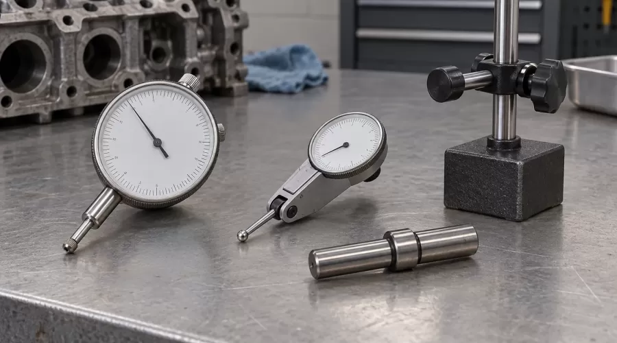
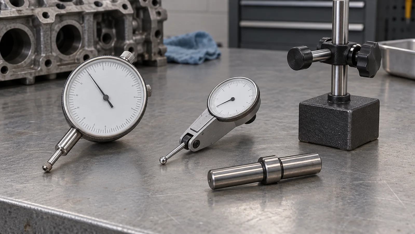
Choose a plunger dial indicator when the intended movement can be followed along its measuring axis with adequate travel and a rigid mounting. Consider a lever test indicator when the contact point is difficult to reach, but follow that instrument's stylus and contact-angle instructions. Neither tool supplies an engine's acceptance limit. Establish the correct reference, check repeatability, and distinguish an observed change from a diagnosis before adjusting or buying parts.
A needle moving beside a miniature shaft looks convincing. It can also make an uncertain setup appear much more precise than it really is. A flexible arm, unsuitable contact angle, dirty surface or misunderstood unit can dominate the reading. The first question is therefore not “How many divisions did it move?” It is “What did this setup actually compare?” This guide helps choose and document an instrument. It does not prescribe runout, endplay or alignment tolerances for an unidentified engine.
Key takeaways
- Plunger and lever instruments have different contact motions.
- Small physical size does not automatically mean suitable range or accuracy.
- Mounting, contact direction and the chosen reference belong in the measurement record.
- Changing a lever stylus can change how its reading should be interpreted.
- A digital minimum/maximum feature is instrument-specific, not universal.
- A repeatable indication is useful evidence, but it is not an engine specification.
Start with the feature, not the dial
Write down what you need to compare: movement in a particular direction, a surface relative to a reference, or variation at a defined location. Outside diameter, an accessible gap and movement of a supported component are different questions. A dial instrument is not a substitute for every dimensional tool. If the task is establishing a size, begin with our caliper versus micrometer guide. If the question is whether a leaf fits a specified gap, use the separate feeler-gauge comparison guide.
Then identify the reference that the engine or component documentation requires. The same surface can produce different observations when supported in different ways. A reading taken from a loosely held assembly cannot simply be compared with a limit defined for a particular fixture or bearing condition. If the relevant method is missing, record the observation as exploratory. Do not turn an exploratory result into a pass or fail by borrowing a number from another model.
Plunger indicators: useful when the direction is accessible
A plunger instrument follows movement through a sliding contact mechanism. Its mounting must allow the intended direction to be measured without side loading or running out of travel. The dial should remain readable while the reference and contact stay stable. A larger-looking range is not always the decisive advantage; the physical arrangement must work around the part being inspected.
Starrett's dial-indicator overview identifies bottom-plunger instruments, several dial sizes and the importance of choosing a suitable readout. That supports selecting for access and readability rather than automatically buying the finest graduation. It does not certify a particular fixture or establish a miniature engine's allowable movement.
Before selecting one, sketch where the body, contact and holder will sit. Check whether the contact can remain in the intended direction throughout the observation. A body that clears the part at the start may collide later. Likewise, a stand that fits the bench may not give the contact enough usable travel. Solve these layout questions before interpreting any reading as a mechanical fault.
Lever test indicators: access with a geometry condition
A lever test indicator uses a pivoting stylus rather than the same sliding motion as a plunger. It can be useful around restricted access, but its geometry must be understood. Do not aim the body merely to make the dial convenient and assume that every stylus angle gives an equivalent result. Follow the exact instrument instructions, including the approved contact and its intended orientation.
Mitutoyo's test-indicator guidance explains the lever comparator, contact-angle considerations, secure mounting and the importance of model-matched stylus length. The practical lesson is to treat angle and stylus identity as part of the setup. A longer replacement tip may reach the surface, but reach alone does not establish correct indication. Stop if its specification cannot be matched.
This is not a reason to avoid lever instruments. It is a reason to plan the measurement around them. If the surface can only be reached at an unsuitable angle, change the fixture or use a different method rather than applying an improvised correction. Any correction should come from the instrument's documented method and a competent measurement plan, not a generic internet multiplier.
Compare both types without assuming interchangeability
| Question | Plunger type | Lever test type | Decision boundary |
|---|---|---|---|
| Contact movement | Sliding measuring axis | Pivoting stylus | Identify the intended movement first |
| Access | Needs space for body and travel | Can reach restricted locations | Reach is not proof of suitable geometry |
| Mounting | Match stem/back and holder | Match specified mounting and stylus | Do not force a nearly matching clamp |
| Reading | Check units, range and revolutions | Check units, range and angle | Record the exact instrument |
| Acceptance | Requires applicable component method | Requires applicable component method | No universal model-engine limit |
TESA's lever-instrument range separates metric and imperial families and lists different inserts and holders. Use that as evidence that accessories and units need exact matching, not as a claim that every listed component can be mixed. Record the model and accessory identity when ordering. A familiar appearance or a similar thread is not enough to guarantee compatibility.
Graduation, resolution and confidence are different
Read the unit before counting divisions. Keep inch and millimetre values distinct in notes, including the markings on any accessory. An analog dial may also require attention to more than one revolution or a separate travel indication. A digital display may offer selectable units or settings. Use the manual to understand the particular instrument rather than assuming its initial screen describes all relevant conditions.
A fine display makes small changes easier to see; it does not by itself make the entire setup accurate to the last digit. Instrument condition, contact behavior, reference quality and mounting stability remain relevant. Repeated identical digits can also reflect limited resolution. Conversely, small reading variation can arise from the setup rather than from a defective engine. Preserve these distinctions when deciding whether more careful measurement is required.
Mahr's MarCator 1087 R-HR specification lists selectable resolution and measurement functions for one particular instrument. The choice is broader than a digital-versus-mechanical label. Match the measurement question and performance requirement, then verify the selected model's specification. This article does not rank brands or imply that an instrument family is automatically better for every bench task.
Build a repeatable setup before recording a result
Inspect the contact, mounting and accessible surface without modifying the component. A damaged contact, loose holder or visibly dirty reference should be resolved through the applicable instructions before measurement. Avoid pressing on a delicate part simply to get a convenient zero. If safe access requires removing guards or disconnecting a powered assembly, follow the engine's procedure and isolate energy before proceeding. Never use a contacting indicator against a running miniature engine.
Check whether the indication returns consistently under the same permitted movement and conditions. Repeat the observation without deliberately changing the mounting or contact location. Keep the sequence and direction consistent where the documented method requires them. If the reading changes when the stand is touched, the result should be held rather than averaged into an apparently precise answer. A stable bench and short, secure mounting are useful setup goals, but their suitability still needs observation.
Record where the contact was placed, the reference used and the assembly condition. A close photograph of the setup can clarify a note, provided it does not replace the method description. Do not claim a calibration check just because the instrument returned to zero. Zero return is one observation. Calibration and traceability require appropriate procedures and evidence beyond that simple check.
Use the A-G-R record
The A-G-R record separates access, geometry and repeatability before an indicator result becomes a repair decision. Access identifies whether the tool can reach the correct feature safely. Geometry identifies the contact direction, reference, instrument and stylus. Repeatability records whether the same permitted observation can be reproduced. This is an editorial documentation framework, not a certified inspection standard.
For access, write the location and any restriction. For geometry, list the instrument model, unit, contact accessory and mounting. For repeatability, preserve the individual observations and the conditions rather than recording only a preferred result. Add the component specification and its source in a separate field. If no applicable limit is available, leave acceptance unknown. That missing field is important evidence, not a paperwork defect to conceal.
For example, “the indication changed over the permitted hand movement at this location” describes an observation. “The shaft is bent” is a causal diagnosis that may require more tests. “Replace the engine” is a purchasing decision requiring additional evidence. Separating those statements prevents one moving needle from deciding a repair that the measurement did not establish.
Minimum, maximum and delta need a defined observation
Some digital instruments provide minimum, maximum or difference functions. Sylvac's S_Dial WORK CBG information lists these functions for that specific family. Do not assume another digital instrument provides identical modes, capture behavior or settings. Check the manual, reset condition and observation interval before relying on a stored extreme.
Even a correctly calculated difference only describes the observation supplied to the instrument. A value captured while the holder moved is not transformed into a valid component result by the display. Likewise, a maximum and minimum do not automatically identify which component caused variation. Record what moved, what remained fixed and how the reading was obtained. Keep any example arithmetic clearly separate from an engine tolerance.
Interpretation: proceed, repeat or stop
Proceed to interpretation only when the method, setup and relevant specification are matched. Repeat or redesign the observation if access, contact or mounting is uncertain. Stop and seek model-specific support if the reading would lead to disassembly, force, machining or a replacement recommendation without adequate evidence. The aim is not to collect numbers at any cost. It is to collect evidence that can support the next bounded decision.
For a coupling problem, our shaft-coupling alignment guide separates several mechanical questions that one reading cannot answer. For an assembly that resists movement, use the bearing shield and seal guide for its own selection question rather than attributing every effect to runout. Neither link supplies a substitute for the exact model's documentation.
Before shopping, record the feature, the suspected component and what remains uncertain. Our thread-identification guide and O-ring measurement guide illustrate separate identity checks. Do not choose a replacement merely because a photograph looks similar. Accurate identification and supported compatibility matter independently of an indicator reading.
Limitations and safety
This guide discusses general comparison-instrument selection. It is not a service instruction for a particular engine, a calibration procedure or a claim of hands-on testing. No universal acceptable runout, bearing clearance or endplay is provided. Do not run, energize or apply fuel to an assembly to obtain a contacting measurement. Do not force a shaft, stylus or clamp. Where the correct method or safe isolation procedure is unknown, stop and obtain qualified help.
Frequently asked questions
Is a dial indicator the same as a lever test indicator?
No. A plunger type has sliding contact movement, while a lever type uses a pivoting stylus. Their access and geometry requirements differ.
Does a finer graduation guarantee a better result?
No. It improves display detail, but setup stability, contact geometry, reference quality and instrument condition still affect the result.
Can I fit a longer stylus to reach a miniature part?
Only when the accessory and interpretation are approved for the exact instrument. Reach alone does not establish correct measurement.
Can one reading prove that a shaft is bent?
No. A reading describes the chosen setup. Establishing the cause requires an appropriate method and consideration of other influences.
Do all digital indicators record minimum and maximum?
No. Available functions and their behavior are model-specific. Check the selected instrument's documentation.
Can I measure against a running model engine?
Do not use a contacting indicator on a running engine. Follow model-specific energy isolation and safe inspection instructions.
What should I do without an engine acceptance limit?
Record the observation and leave acceptance unknown. Obtain the applicable specification instead of importing a limit from a different model.
Conclusion
Choose an indicator by access, geometry and the required comparison, not by the number of digits or the shape of its case. Preserve setup details and repeatability before turning an observation into a diagnosis. An honest unknown is more useful than an unsupported pass, and a well-defined measurement question is the best starting point for a sensible repair decision.
Leave a comment