

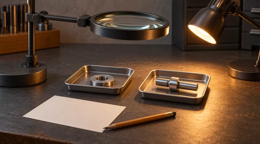
By EnginesDIY · October 18, 2026 · Workshop observation guide
Quick answer
For model-engine visual inspection, choose a view that shows the feature clearly while preserving its location on the part. Start with an overview, improve lighting, then increase magnification only if necessary. A larger image can help document a mark; it does not by itself establish the mark's depth, the part's dimensions, or whether the part is safe to reuse. Stop when interpretation requires a manufacturer limit, a different measurement method or a qualified assessment.
The L-V-R record separates location, viewing conditions and review decisions before a visible mark becomes a repair claim. It is an organizing method for communicating observations, not a certified inspection procedure. It can help a hobbyist send a useful question to a supplier without turning an uncertain photograph into an unsupported diagnosis.
Key takeaways
- Keep an overview that identifies the component and orientation before making close-ups.
- Change one viewing condition at a time and preserve the original images.
- Record what is visible separately from what you think caused it.
- Do not treat screen enlargement, sharpness or dramatic contrast as a measurement.
- Use the exact model documentation for service decisions; uncertain critical parts stay out of use.
Define the question before selecting a lens
A question such as “Can you read the marking on this loose washer?” is different from “Is this shaft within tolerance?” The first concerns recognition. The second needs defined dimensions, a suitable instrument and an acceptance limit. Buying more magnification does not bridge that gap automatically. Decide whether you need to identify a feature, document a surface, measure a dimension or obtain an authorized reuse decision.
Write that question beside the model name, revision and component location. An unidentified part with an excellent close-up is still unidentified. If several similar parts are on the bench, keep them in separate labelled containers and connect each image to one container. Do not rely on remembering which nearly identical item was photographed first.
This distinction also prevents unnecessary purchases. A readable marking may resolve an identification question without a microscope. A hidden internal feature may remain inaccessible regardless of the lens you buy. No viewing accessory makes unapproved disassembly, forced rotation or destructive inspection appropriate. Follow the model instructions and preserve warranty or service evidence where applicable.
Understand field of view and working clearance
Magnification is only one part of a usable view. Edmund Optics' magnifier selection guide describes tradeoffs among power, viewing area and lens design. A practical implication is to judge whether the relevant feature and enough surrounding context are visible together, rather than selecting solely by the largest advertised magnification number.
Check whether the lens, lamp or stand crowds the part. Evident explains working distance as the space between the focused sample and objective. Its industrial examples illustrate why clearance matters; their numerical examples are not requirements for your model or permission to manipulate components beneath a lens.
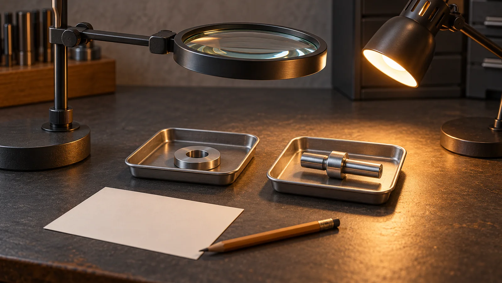
For a small removable part, a stable support can make observation less confusing than repeatedly holding the object at a different angle. Keep the support from obscuring the relevant edge. Avoid clamping delicate sealing faces or rolling elements simply to obtain a photograph. If the component cannot be supported without risk, document the limitation and use the service route instead.
Lighting changes the evidence you see
A bright reflection can hide a feature, while a strong shadow can exaggerate an edge. Leica's industrial illumination guide distinguishes lighting approaches for different surface shapes and inspection questions. The relevant principle here is that illumination affects contrast: one attractive image is not a complete account of a surface.
For documentation, retain a broad, evenly lit view and a second view with a changed light direction when that is safe and useful. Keep the part orientation traceable. Describe the change in words, such as “lamp moved from left to right,” rather than suggesting that a darker line necessarily became deeper. Do not use a single dramatic shadow to assign a wear mechanism.
Do not shine intense light into your eyes or use a magnifier to concentrate sunlight. Keep lamps away from fuel, heat-sensitive materials and flammable cleaning products. An inspection image does not justify applying solvents, abrasives or compressed air. Cleaning instructions and observation instructions are separate; when cleaning is not authorized, record the surface as received.
A simple L-V-R observation record
Use one short record per part, with three distinct sections. Location identifies what was viewed. Viewing conditions describe how the record was made. Review identifies the unanswered question and who can answer it. This separation makes uncertainty visible rather than burying it in a confident filename such as “cracked-shaft-final.”
| Section | Record | Do not infer |
|---|---|---|
| Location | Model, revision, part identifier, orientation and overview image | Compatibility from appearance alone |
| Viewing conditions | Lens or camera, light direction, image settings and original filename | Dimensions from screen size |
| Review | Visible feature, uncertainty, required document or supplier question | Safe reuse from a clear photograph |
A useful location description might be “loose spacer from the front support assembly, face toward the pulley, container B.” That is more reproducible than “the shiny ring.” If the original orientation was not recorded, say so. Do not reconstruct an assembly position by guesswork just to complete the form.
For viewing conditions, distinguish optical settings from later cropping. Preserve the unedited file and give any annotated version a different name. For review, write “line visible near shoulder; cause not established” rather than “fatigue crack” unless qualified evidence supports that conclusion. The objective is a reliable handoff, not an impressive diagnosis.
Capture context before detail
Begin with the whole component and its label. Then make a closer view that still shows a recognizable reference feature. Finally, document the area of interest. Keep filenames or a short index connecting those views. A close-up without orientation can make an ordinary machining transition look like an unexplained defect because its relationship to the rest of the part has disappeared.
Where focus is limited, take separate clearly identified views rather than treating an out-of-focus area as smooth. ZEISS describes stereo viewing and zoom in its Stemi 508 system. That is context for understanding viewing tools, not evidence that a hobby camera reproduces a stereo microscope or that every visible plane has been inspected.
Likewise, Vision Engineering's ProteQ VISO system illustrates that industrial inspection platforms combine viewing arrangements and working space. This guide does not recommend that instrument, claim equivalence with a desk magnifier, or transfer its capabilities to an unknown setup. Document the equipment you actually used, not an idealized laboratory capability.
Do not convert a photograph into an unearned measurement
A visible scale beside a part can provide context, but the image may contain perspective, lens distortion or a different plane of focus. Without an appropriate validated method, do not report the resulting pixel estimate as a tolerance measurement. Even a sharp photograph cannot establish dimensions hidden behind an edge or below the surface.
If the question is dimensional, move to the appropriate measurement workflow rather than adding digital zoom. Our caliper versus micrometer guide explains a different evidence task. For displacement questions, the dial and test indicator guide separates instrument roles. None of those tools supplies an acceptance specification by itself.
Keep the observation and measurement records linked but distinct. A report can correctly say that a surface line was photographed and that a separately measured diameter was recorded. It cannot conclude that the line caused the diameter result merely because the two observations concern the same component.
Three hypothetical workshop decisions
Consider a loose screw with an uncertain recess. An overview and a well-lit close-up may help identify which drive family needs further verification. They do not prove that the recess is undamaged or that a particular bit fits correctly. Use the screw drive identification guide before applying torque; do not force a tool to test a photographic guess.
Next consider a locating pin with a visible band. Record the band and its position without declaring it a wear limit. The model's specification determines whether dimensions and surface condition are acceptable. The locating pin identification and fit guide explains why identity and fit are separate from visual similarity.
Finally, consider an unopened spare bearing with an unclear label. Improve the label photograph without opening the bearing or removing its shields for a better picture. The spare bearing storage guide and bearing shields and seals guide address handling and configuration. A good image should preserve evidence, not create a new contamination risk.
The same evidence boundary applies to wiring: a visible connector mark is not proof of electrical performance. Our continuity versus load-test guide keeps those separate questions distinct. Do not connect a supply simply to investigate a visual observation.
Know when the inspection must stop
Stop if the part is hot, connected to an energy source, contaminated by an unknown substance or unsafe to handle. This article concerns stationary, safely accessible components. It is not a procedure for observing a running engine, opening a pressure vessel, testing fuel equipment or placing a lens near rotating machinery. Follow the exact equipment instructions for isolation and service.
Also stop when the decision concerns a suspected crack, a safety-critical load path, an unknown service limit or a feature that cannot be viewed reliably. Keep the component out of service pending competent guidance. Do not polish away the evidence, probe a mark with a sharp tool or improvise a chemical test from a photograph.
Give the supplier a focused request: identify the model and part, attach the overview and original detail files, describe the viewing conditions, and ask what official inspection method or replacement criterion applies. If no criterion is available, the honest outcome is unresolved, not “passed because nothing obvious was seen.”
Frequently asked questions
What magnification should I buy for model-engine inspection?
There is no universal number for every component and question. First determine the required viewing area, clearance and documentation task. Try a view that preserves context; increase magnification only where it resolves a specific uncertainty. Manufacturer service requirements take precedence over a general buying suggestion.
Does a clear close-up prove a part is crack-free?
No. It records a particular visible surface under particular conditions. It does not rule out hidden damage or establish that an appropriate crack-detection method was performed. A suspected critical defect requires qualified review rather than reassurance from image sharpness.
Can I use my phone instead of a microscope?
A phone may document labels, orientation and visible features adequately for a supplier question. Do not claim microscope resolution, stereo depth perception or calibrated measurement from that fact. State the actual setup and retain original files so the recipient can judge their usefulness.
Why does a mark disappear when I move the lamp?
Its contrast may depend on illumination and viewing geometry. That change alone does not identify the material condition or show that the feature has physically disappeared. Keep both views and describe the light change rather than assigning a cause.
Should I clean a part before photographing it?
Only according to the applicable instructions and with appropriate authorization. Photographing the as-received condition can preserve useful evidence. Unknown residues, delicate coatings and sealed components need specific handling guidance; better-looking pictures are not a reason to improvise cleaning.
Can I sharpen or annotate an inspection image?
Keep the original and label edited copies. An arrow can identify an area for discussion, but aggressive sharpening or contrast changes can alter apparent edges. Do not present an enhanced image as an untouched record or use editing to claim a measured defect size.
What should I send when asking about a replacement?
Send the exact model and revision, the part identifier if known, an overview, a detail view, viewing conditions and the unanswered question. Include separate verified measurements where relevant. Ask for the approved replacement and criterion; do not order solely from a close visual resemblance.
Conclusion: a useful view supports a better question
Good visual documentation is deliberately modest about what it proves. It helps identify where to look, preserves the conditions of observation and makes uncertainty easy to communicate. It does not replace a drawing, a measurement method or a service decision. Use the L-V-R record to keep those boundaries visible, and stop before an ambiguous mark becomes an unsupported repair instruction.
The five linked primary references explain optical viewing concepts, not the service limits of a specific engine. Our workshop examples are hypothetical applications of an evidence-recording approach, not reported experiments, certified inspections or compatibility guarantees.
Leave a comment